Compteur Pour Afficheur 7 segments / 7-segment Display Counter
Les circuits logiques / Logic circuit
BCD conteur avec Affichage Octal conteur avec Affichage Décade conteur avec Affichage
Decade down conteur avec Affichage Accès aléatoire avec Affichage
Binary counter with display 0-99 4 x 7 seg Countdown Timer
| Les afficheurs
7 segments peuvent être utilisés simultanément pour afficher les
chiffres de 0 à 9, ainsi que quelques caractères, pour une utilisation
dans un circuit de comptabilité ou pour être connectés à un
microcontrôleur. De nos jours, il est très facile d'afficher des chiffres et des lettres sur plusieurs afficheurs LED à l'aide de microcontrôleurs, tels qu'Arduino ou Raspberry Pi, et d'un court programme informatique permettant d'afficher les chiffres souhaités. Cependant, il arrive, en tant qu'étudiant en électronique ou amateur, que l'on souhaite afficher deux chiffres ou plus dans le cadre d'un projet ou d'un circuit logique numérique. Comment procéder ? |
7-segment
Displays can be used together to display digits from 0 to 9 as well as a
few characters for use in acounting circuit or interfaced to a
microcontroller. Nowadays it is very easy to display numbers and letters across multiple LED displays using micro-controllers, such as the Arduino or Raspberry-Pi, along with a small bit of software related code to display the required digits. But sometimes as an Electronics student or hobbyist we want to display two or more numbers or digits as part of our project or digital logic circuit. So how can we do this? |
| Les afficheurs
7 segments offrent une solution pratique pour afficher des informations
numériques de zéro à neuf. Ils sont constitués d'un ensemble de diodes électroluminescentes (DEL) connectées entre elles dans un seul boîtier. Chaque DEL (appelée segment) est illuminée par un courant électrique. En allumant différentes combinaisons de segments (certains allumés et d'autres éteints), on peut afficher des caractères ou des chiffres. Les DEL sont semblables aux diodes classiques : elles ne laissent passer le courant que dans un seul sens. La différence réside dans le fait qu'une DEL émet de la lumière à partir de sa jonction PN lorsqu'un courant électrique la traverse. Ce phénomène d'électroluminescence se produit lorsque la tension entre l'anode (A) et la cathode (K) est supérieure d'environ 2 volts à la tension entre ces deux bornes. Le courant d'alimentation typique nécessaire pour alimenter une LED se situe entre 6 mA et 20 mA environ. Sa valeur est généralement contrôlée par une résistance en série avec la LED. Ainsi, en polarisant en direct l'un des segments de la LED d'affichage (anode vers l'alimentation, borne positive, et cathode vers la masse, borne négative), on peut obtenir un affichage aléatoire de segments ou un chiffre décimal de 0 à 9, fournissant ainsi un résultat visuel pour notre projet. |
7-segment
displays provide a convenient way of displaying numerical information
from zero to nine. As they basically consist of a load of light emitting diodes connected together within a single indicator package. Each light emitting diode (called a segment) is illuminated using an electrical current. And by illuminating various combinations of segments so that some segments will be turned “ON” and emitting light while others will be turned “OFF” we can display individual characters or numbers. The Light Emitting Diode, LEDs are just like normal diodes, in that they only allow current to flow in one direction. This difference between the two is that an LED emits light energy from its PN-junction when an electrical current passes through it. This electroluminescence action occurs whenever the Anode (A) terminal of the LED is more positive than its Cathode (K) terminal by approximately 2 volts. The typical supply current required to illuminate an LED junction ranges from between about 6mA to 20mA. And whos value is commonly controlled using a resistor in series with the LED. So by forward-biasing any one of the displays LED segments so that the anode terminal is towards the supply (positive) and the cathode terminal is towards ground (negative), we can produce a set of randomly lit segments or a decimal number from 0 to 9 providing a visual output for our project. |
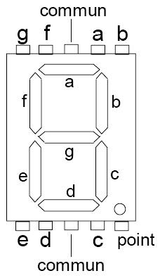
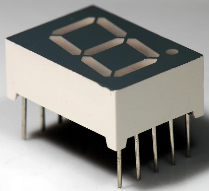
| Afficheur 7
segments Comme son nom l'indique, un afficheur 7 segments est composé de sept segments, c'est-à-dire de sept diodes électroluminescentes (DEL), qui, ensemble, forment un chiffre complet. En réalité, la plupart des afficheurs 7 segments contiennent huit DEL internes, la huitième servant à afficher la virgule décimale, généralement dans un coin inférieur. Donc, si un afficheur 7 segments est composé de sept DEL (sans tenir compte de la virgule décimale pour l'instant), une DEL par segment, et qu'une DEL possède deux bornes (anode et cathode), cela signifie-t-il que chaque afficheur 7 segments possède 14 broches de connexion ? La réponse est non. Bien qu'un segment puisse être allumé individuellement, une borne de chaque DEL interne est reliée à un point commun. Ainsi, au lieu de 14 broches de connexion pour l'afficheur, nous n'en aurons que huit (7 + 1). Une broche est dédiée à chacune des sept LED, plus une broche commune. C'est cette broche commune qui détermine le type et le nom de l'afficheur 7 segments. Lorsque les cathodes de toutes les LED de l'afficheur sont connectées ensembles, on parle d'afficheur à cathode commune (CC). De même, lorsque les anodes de toutes les LED de l'afficheur sont connectées ensembles, on parle d'afficheur à anode commune (CA). Un afficheur 7 segments peut donc être soit à cathode commune (CC), soit à anode commune (CA). |
7-Segment
Display As its name suggests, a 7-segment display consists of seven segments, meaning it consists of seven light emitting diodes or LED’s, which together can be used to form one complete digit on the display. Actually, most 7-segment displays contain eight internal LED’s as the eigth one is used for a decimal point, usually in one of the bottom corners of the display. So if a 7-segment display consists of seven LED’s (ignoring the decimal point for now). One for each segment, and an LED has two terminals, an Anode and a Cathode, does that mean that each single 7-segment display will have 14 connecting pins or terminals. Well the answer is, No. While an LED segment can be illuminated individually as required, one terminal of each internal LED is connected to a common point or node. Thus instead of having 14 connecting pins for the display we will only have only eight (7 + 1) pins. One each for the seven individual LEDs plus a common pin, and it is this “common pin” which identifies the type and name of 7-segment display. When the cathode terminals of all the LEDs used in the display are shortedtogether, the display is referred to as a Common-cathode, (CC) display. Likewise, when all the anode terminals of the LEDs used in the display areshorted together, the display is referred to as a Common-anode, (CA) display. Thus a 7-segment display can be either a Common Cathode (CC) or a Common Anode (CA) type display. |
 |
Common Anode (CA) Configuration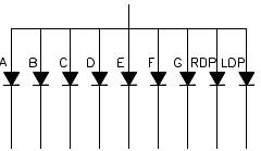 Common Cathode (CC) Configuration 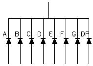 |
|
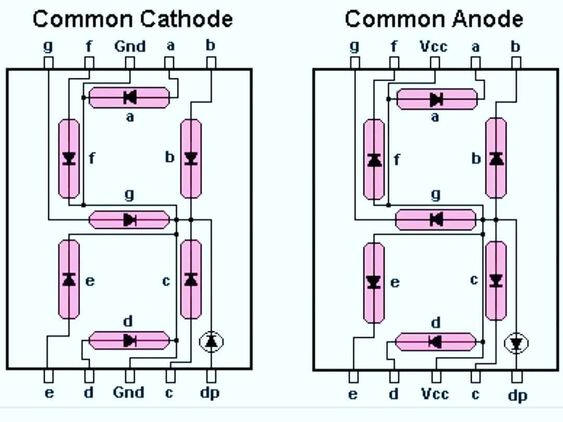
Configuration à cathode commune (CC) Affichage à cathode commune (CC) – Dans un afficheur à cathode commune, toutes les cathodes (K) des segments LED sont reliées entre elles et connectées à la masse (0 volt). L'éclairage de chaque segment est obtenu par l'application d'un courant électrique approprié polarisant en direct les anodes (a à g). Un afficheur à cathode commune nécessite donc un circuit de commande capable de fournir le courant nécessaire. |
Common Cathode (CC) Configuration The Common Cathode (CC) Display – In the common cathode display, all the cathode (K) connections of the LED segments are tied together and connected to ground or zero-volts. The individual segments are illuminated by the application of a suitable electric current to forward bias the individual Anode terminals (a to g). Thus common cathode display requires a driving circuit that can source a current. |
|
Configuration à anode commune (CA) Affichage à anode commune (AC) – Dans un affichage à anode commune, toutes les connexions anode (A) des segments LED sont reliées à une alimentation positive. L'allumage de chaque segment est obtenu en appliquant un signal de masse (niveau bas) à sa borne de cathode (a à g). Un affichage à anode commune nécessite donc un circuit de commande capable d'absorber le courant. |
Common Anode (CA) Configuration The Common Anode (CA) Display – In the common anode display, all the anode (A)connections of the LED segments are joined together to a positive voltage supply. The individual segments are illuminated by applying a ground, or “LOW” signal to the Cathode terminal of the particular segment (a to g). Thus a common anode display requires a driving circuit which can sink a current. |
| Il existe
plusieurs façons de connecter plusieurs afficheurs LED 7 segments à un
circuit électronique, chacune présentant ses propres avantages. Chaque segment nécessitant un courant d'environ 6 à 20 milliampères (mA) pour fonctionner à luminosité normale, et un afficheur comportant sept segments (plus un point décimal), on utilise généralement des circuits intégrés de décodage/pilotage dédiés pour piloter chaque segment directement. Les circuits intégrés de décodage convertissent un type de données d'entrée en un autre. Différents types de décodeurs numériques sont disponibles selon le type de données d'entrée (binaire, BCD ou hexadécimal) et le code de sortie requis, représentant le nombre de lignes de sortie décodées. Par exemple : 3 vers 8 lignes, 4 vers 16 lignes, etc. Dans notre cas, nous avons besoin d'un circuit intégré de décodage capable de convertir un code binaire en un ensemble de signaux de sortie pour piloter un afficheur 7 segments, tel qu'un décodeur BCD vers 7 segments. Le codage décimal binaire, ou BCD en abrégé, est un ensemble de chiffres binaires de 4 bits utilisé pour représenter les 10 chiffres décimaux de 0 à 9 avec la liste suivante de puces de décodage IC capables de faire exactement cela. |
There are many
different ways to connect multiple 7-segment LED displays to an
electronic circuit, with each one having its own advantages. Because each individual segment requires about 6 to 20 milli-amperes (mA) of current to illuminate it for normal brightness, and as there are seven segments (plus a decimal point), generally dedicated decoder/driver chips are used to drive each display directly. IC decoder chips basically convert one type of input data into another type. And there are different types of digital decoders available depending upon the type of input data (such as binary, BCD, or hex), and the required output code representing the number of decoded output lines. For example: 3-to-8 lines, 4-to-16 lines, etc. In our case we require a decoder chip which can convert some binary code into a set of output signals to drive a 7-segment display such as a “BCD-to-seven-segment decoder”. Binary Coded Decimal, or BCD for short, is a set of 4-bit binary digits used to represent the 10 decimal digits from 0 to 9 with the following list of IC decoder chips which are able to do just that. |
| TTL Decoder
IC’s 74LS47 Common Anode (AC) 74LS48 Common Cathode (CC) 74LS247 Common Anode (AC) |
CMOS
Decoder IC’s 74HC4511 Common Cathode (CC) 4511 Common Cathode (CC) CD4513 Common Cathode (CC) 4026 CC (7 segment dysplay decade counter) |
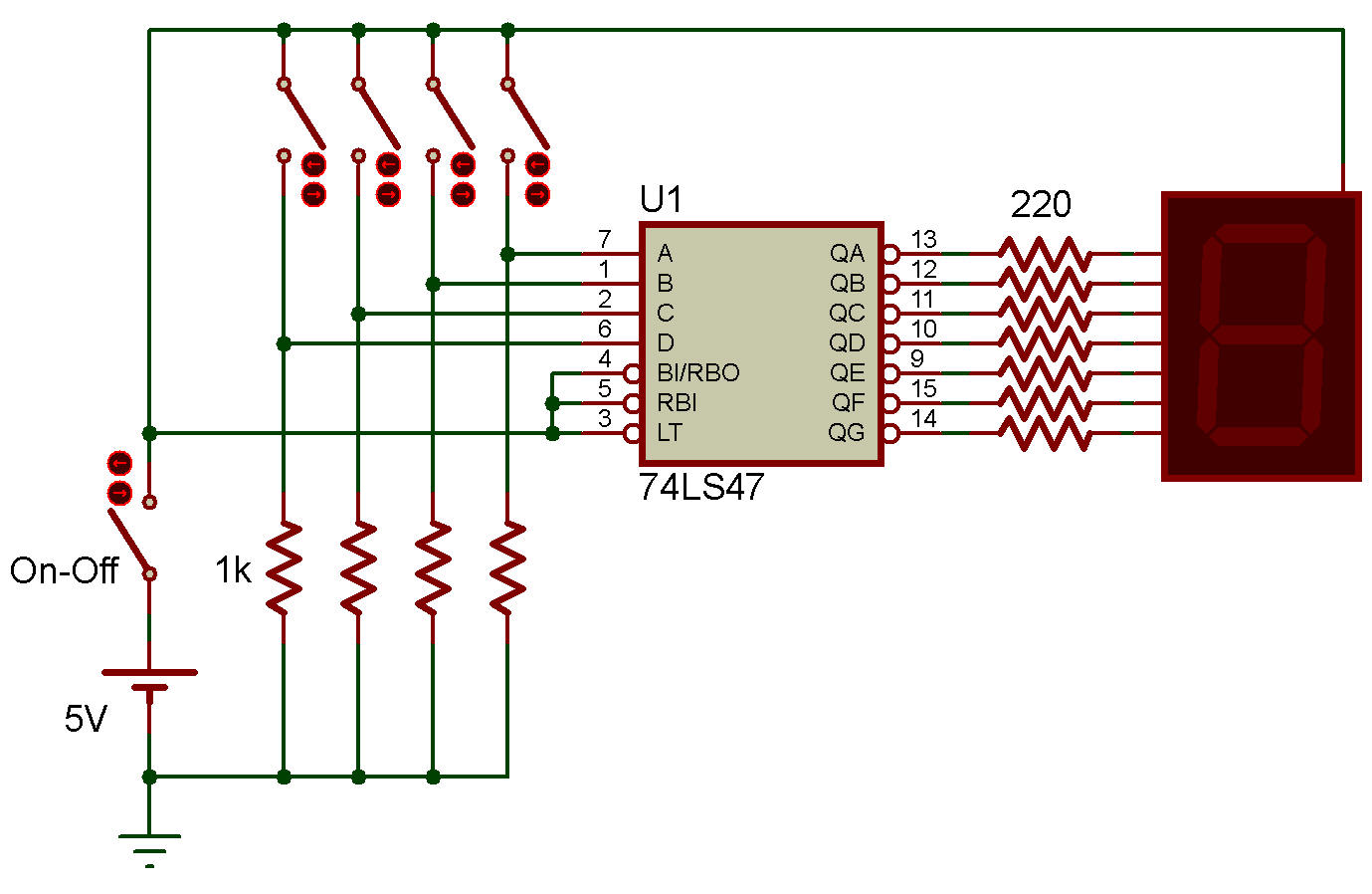
| Le circuit
intégré décodeur 7 segments TTL 74LS47 est de loin le plus répandu et
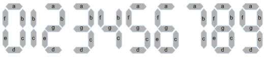
est capable de piloter des afficheurs à anode commune (CA). Le TTL 74LS47 possède une entrée BCD 4 bits et sept sorties actives « BAS » individuelles pour piloter chacun des sept segments LED. Une sortie active « BAS » signifie que la broche de sortie est mise à la masse (0 V) pour allumer un segment LED, tandis qu'une sortie « HAUT » éteint le segment LED. La série d'afficheurs HDSP est un bon point de départ, mais tout afficheur à anode commune standard conviendra (et le choix est vaste). À l'aide de quatre interrupteurs, un nombre binaire de 4 bits est appliqué aux entrées BCD A, B, C et D du décodeur 74LS47 pour produire les signaux de sortie a, b, c, d, e, f et g qui pilotent l'afficheur 7 segments et affichent les chiffres de 0 à 9, comme illustré. |
The TTL 74LS47
is the most popular 7-segment decoder IC by far and which is capable of
driving common anode (CA) displays. The TTL 74LS47 has a 4-bit BCD input and seven individual active “LOW” outputs for driving each of the seven LED segments. Active “LOW” means the output pin switches to ground (0V) to light an LED segment, while a “HIGH” output will turn the LED segment “OFF”. The HDSP series of displays is a good starting point but any standard common anode display will do, (and there are plenty to choose from). With the aid of four switches, a 4-bit binary number is applied to the BCD inputs A, B, C and D of the 74LS47 decoder to produce the output signals a, b, c, d, e, f and g used to drive the 7-segment display generating the required numbers from 0 to 9 as shown. |
|
Le code Binaire
/
Binary
Code Le code Binaire Suite... DCBA = n 0000 = 0 0001 = 1 0010 = 2 0011 = 3 0100 = 4 0101 = 5 0110 = 6 0111 = 7 1000 = 8 1001 = 9 |
|
 |
|
| La connexion
entre le décodeur/pilote 74LS47 et l'afficheur à anode commune nécessite
sept résistances (huit si l'on inclut la virgule) pour limiter le
courant. Pour que chaque segment LED de l'afficheur s'allume correctement, le courant qui le traverse doit être contrôlé avec précision. La meilleure méthode pour limiter le courant dans un segment consiste à utiliser une résistance de limitation de courant en série avec chacun des sept segments LED, comme illustré. Sans résistance en série, le courant serait maximal et la LED brillerait intensément pendant un court instant avant d'être définitivement détruite. Chaque segment LED d'un afficheur 7 segments classique est conçu pour fonctionner avec un courant compris entre 6 et 20 mA, ce qui correspond à une chute de tension d'environ 1,8 volt à ses bornes pour une luminosité normale. Il est possible de calculer la valeur de la résistance de limitation de courant nécessaire pour obtenir le courant requis par segment LED. Un afficheur 7 segments est constitué de plusieurs LED individuelles intégrées dans un boîtier rectangulaire et que chaque segment nécessite une résistance en série pour limiter son courant continu direct. Pour un afficheur à anode commune, les anodes de chaque segment LED sont reliées à une alimentation de 5 volts (VS). Si, lorsque la LED est allumée, la chute de tension directe à sa jonction est d'environ 1,8 volt, la tension aux bornes de la résistance en série est également de 1,8 volt : VS – VLed = 5 – 1.8 = 3.2 volts La valeur de la résistance nécessaire pour limiter le courant d'un segment se calcule donc simplement à l'aide de la loi d'Ohm, en fonction du courant requis pour l'allumer. On peut ainsi calculer la plage de résistances nécessaire pour limiter le courant de la LED entre 6 mA et 20 mA, quelle que soit l'application et l'intensité lumineuse souhaitées: |
The connection
between the 74LS47 decoder/driver and the common anode display, requires
seven resistors (eight if the decimal point is included) to limit
current flow. For each LED segment of the display to light properly, the flow of current through each segment needs to be carefully controlled. The best method of limiting the current through a displays segment is to use a current limiting resistor in series with each of the seven LED segments as shown. If we do not use a series connected resistor, maximum current would flow and the LED would be very bright for a short period of time, before becoming permanently destroyed. As each LED segment of a typical 7-segment LED display is rated to operate at between 6 to 20mA offering a voltage drop across the LED’s diode junction of about 1.8 volts for normal brightness. We can calculate the value of the current-limiting resistor needed to produce the required current per LED segment. A 7-segment display is basicaslly a bunch of individual LED’s within a single rectangular package and that LED’s require a series resistor to limit their DC forward current per segment. For a common-anode display, the anodes of each LED segment are connected together to a 5 volt supply, (VS). If when illuminated the forward voltage drop across the LED’s junction is about 1.8 volts, then the voltage across the series resistor must be equal too: VS – VLed = 5 – 1.8 = 3.2 volts So the resistive value required for the series current limiting resistor of a single segment is simply found using Ohm’s Law at the required current flow to illuminate it. Therefore we can calculate the range of resistance required to limit the LED’s current to between 6mA and 20mA for whatever application and LED intensity we want as follws: |
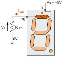 |
R(6mA) =
(VS – VLed) / ILed = (5 – 1.8) / 0.006 = 533Ω R(20mA) = (VS – VLed) / ILed = (5 – 1.8) / 0.02 = 160Ω |
| Ainsi, pour un
courant de 6 mA, il faudrait une résistance de limitation de courant en
série de 533Ω, ou de 560Ω à la valeur la plus proche. Pour limiter le courant à 20 mA, une résistance de 160Ω serait nécessaire. En pratique, toute résistance standard de valeur appropriée comprise entre 220 Ω et 360 Ω peut être utilisée pour alimenter un afficheur 7 segments sous 5 volts ; le choix dépend des résistances disponibles. Bien que nous utilisions ici un afficheur LED à anode commune comme exemple, les mêmes calculs et valeurs de résistance sont valables pour les afficheurs LED à cathode commune. Les réseaux de résistances en boîtier DIP (Dual-In-Line Package) sont couramment disponibles ; ils contiennent les sept (ou huit) résistances dans un seul boîtier, ce qui simplifie le câblage entre le circuit intégré de commande et l’afficheur. Notez également que, bien que nous ayons utilisé ici le circuit intégré décodeur/pilote BCD vers 7 segments TTL 74LS47 avec ses sorties actives à l'état bas (puits de courant) pour piloter un afficheur à anode commune, le circuit intégré décodeur/pilote BCD vers 7 segments TTL 74LS48 est identique, à la différence qu'il est conçu pour piloter un afficheur à cathode commune, car il produit des sorties actives à l'état haut (source de courant). Ainsi, selon le type d'afficheur LED 7 segments dont vous disposez, vous aurez peut-être besoin d'un circuit intégré 74LS47 pour piloter, par exemple, un afficheur LT542 CA, ou d'un circuit intégré 74LS48 pour piloter son équivalent, le LT543 CC. Le choix vous appartient. |
Thus at 6mA
current we would require a series current limiting resistor of 533Ω, or
560Ω to the nearest preferred value. And to limit the current to 20mA we would require a resistor of 160Ω. In reality, any good standard preferred resistor value of between 220Ω and 360Ω could be used to illuminate a 7-segment display from a 5 volt supply, it all depends on what resistor values you have available. Although here we are using a common anode LED display as our example, the same calculations and resistive values are also true for the common cathode LED displays. Dual-in-line package (DIP) resistor networks are commonly available with all seven (or eight) resistors within in a single DIP package simplifying the wiring process between driver IC and display. Note also that while we have used here the TTL 74LS47 BCD to 7-segment decoder/driver IC with its active LOW (current sink) outputs for driving a common anode display, the TTL 74LS48 BCD to 7-segment decoder/driver IC is exactly the same except that it designed to drive a common-cathode display as it produces active HIGH (current source) outputs. So depending upon which type of 7-segment LED display you have you may need a 74LS47 IC for driving, let’s say for example a LT542 CA display, or a 74LS48 IC for driving its equivalent LT543 CC display. The choice is yours. |
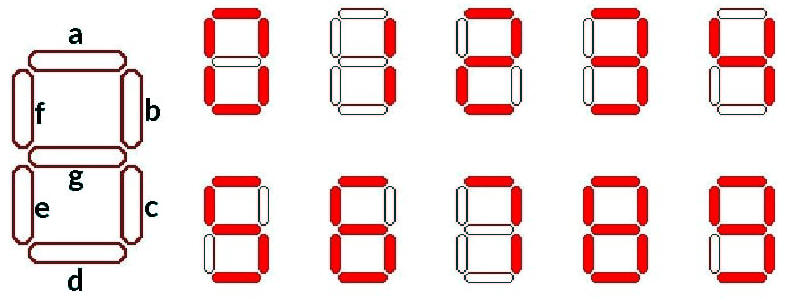
| Affichage
de chiffres sur un afficheur 7 segments Le 74LS47 possède quatre entrées pour les chiffres BCD (8-4-2-1) A, B, C et D, et des sorties pour chacun des segments de l'afficheur 7 segments. L'actionnement des quatre interrupteurs SA, SB, SC et SD génère la séquence d'entrée nécessaire à l'activation des segments LED correspondants à l'affichage du chiffre. En fonctionnement normal, les broches LT (test de lampe), BI/RBO (entrée de suppression/sortie de suppression par ondulation) et RBI (entrée de suppression par ondulation) du 74LS47 sont toutes connectées à l'alimentation +5 V (niveau haut). Les chiffres affichés sont donc les suivants : |
Displaying
Numbers on a 7-segment Display The 74LS47 has four inputs for the BCD (8-4-2-1) digits A, B, C and D, and outputs for each of the segments of the seven-segment display. Operation of four switches SA, SB, SC and SD , will generate the necessary input sequence to activate the appropriate LED segments responsible for displaying the corresponding number. For normal operation, the LT (Lamp test), BI/RBO (Blanking Input/Ripple Blanking Output) and RBI (Ripple Blanking Input) of the 74LS47 are all connected to the +5V supply (HIGH). Thus the numbers displayed are as follows: |
 |
|
| Affichage 7
segments pour les dix chiffres Bien que l'utilisation des quatre interrupteurs SPST permette d'afficher les chiffres correspondants ou des caractères aléatoires, leur manipulation simultanée peut s'avérer fastidieuse. Il serait donc préférable de disposer d'une seule puce capable de générer l'information binaire sur 4 lignes sans utiliser les quatre interrupteurs : le compteur BCD 74LS90. Le circuit intégré 74LS90 peut être configuré comme un compteur décimal modulo 10 (division par 10) pour produire un code de sortie BCD, comptant de 0000 à 1001 puis se réinitialisant à 0000. Grâce à ce circuit intégré compteur/diviseur décimal asynchrone, il est possible d'incrémenter les chiffres de l'afficheur 7 segments à l'aide d'un seul interrupteur, comme illustré. |
7-Segment
Display Elements for all Ten Number Digits While the operation of the four SPST switches will cause the corresponding numbers or random characters to display, it can be a bit tedious operating the four switches at a time. So it would be better if we had a single IC chip that was able to generate the 4-line binary information without using the four switches, and there is, the 74LS90 BCD Counter. The 74LS90 integrated circuit that can be configured as a MOD-10 decade (divide-by-10) counter to produce a BCD output code, counting from 0000 to 1001 and then resets itself back to 0000. By using this asynchronous decade counter/divider IC, we can increment the digits on the 7-segment display using just one single switch as shown. |
 |
|
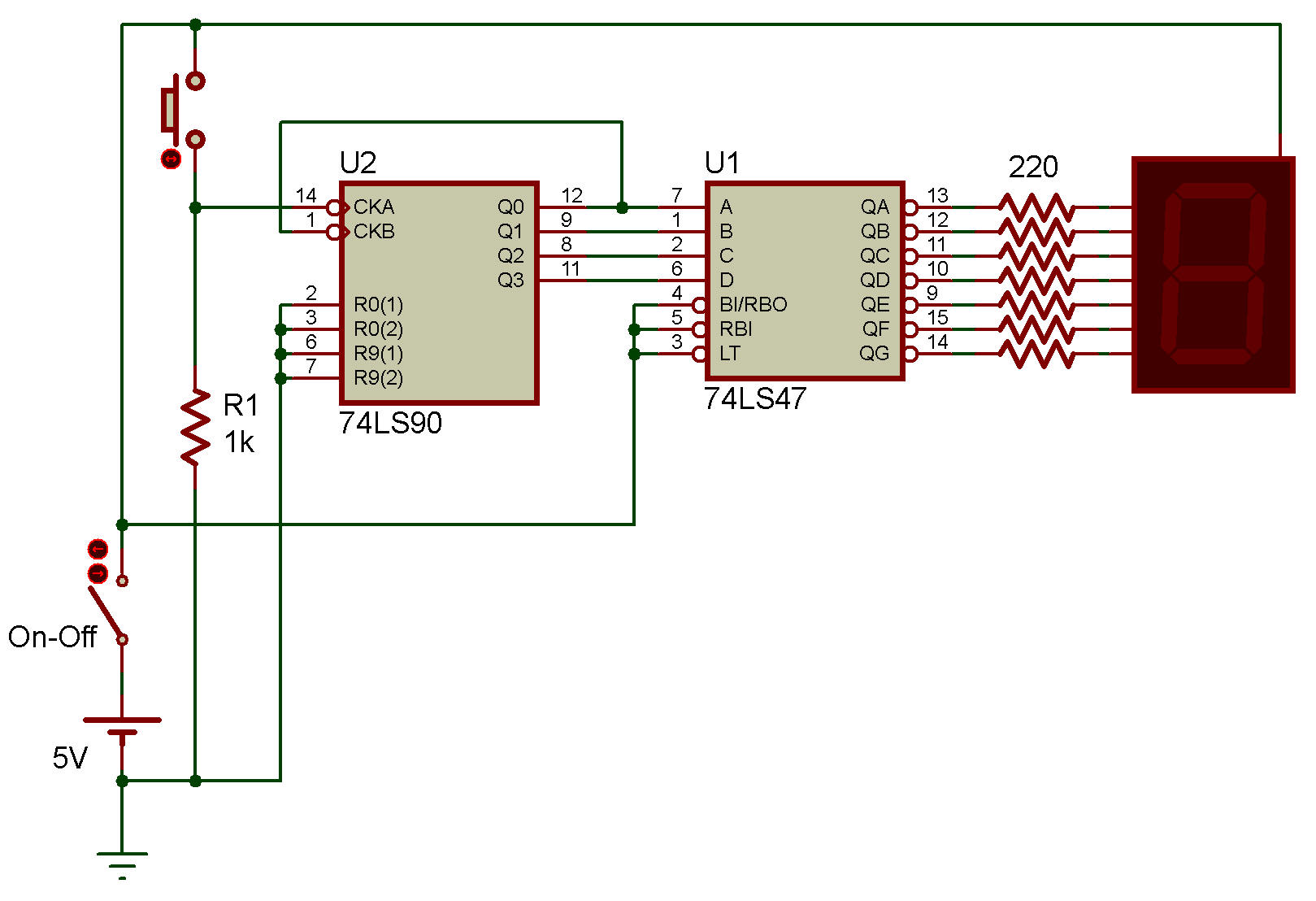
| Il est
désormais possible d'incrémenter l'affichage de 0 à 9 en appuyant dix
fois sur le bouton-poussoir. En modifiant la position du bouton-poussoir et de la résistance de 1 kΩ, le comptage peut s'effectuer aussi bien à l'appui qu'au relâchement du bouton. Ce circuit simple illustre la réalisation d'un compteur numérique de 0 à 9 à l'aide d'un compteur BCD 74LS90 et d'un pilote d'afficheur 7 segments 74LS47. Ce compteur à un chiffre (0 à 9) peut être étendu en ajoutant un second étage de comptage pour obtenir un compteur à deux chiffres (00 à 99). |
We can now
increment the numbers on the display from 0 to 9 by simply pressing one
pushbutton switch ten times. By changing the position of the push button and 1kΩ resistor, the count can be made to change on either the activation or the release of the pushbutton. Our simple circuit shows how we can produce a 0 to 9 digital counter using a 74LS90 BCD Counter and a 74LS47 7-segment display driver. But this single-digit 0 to 9 counter can be extended with the addition of a second counter stage to make a two-digit 00 to 99 counter. |
 |
|
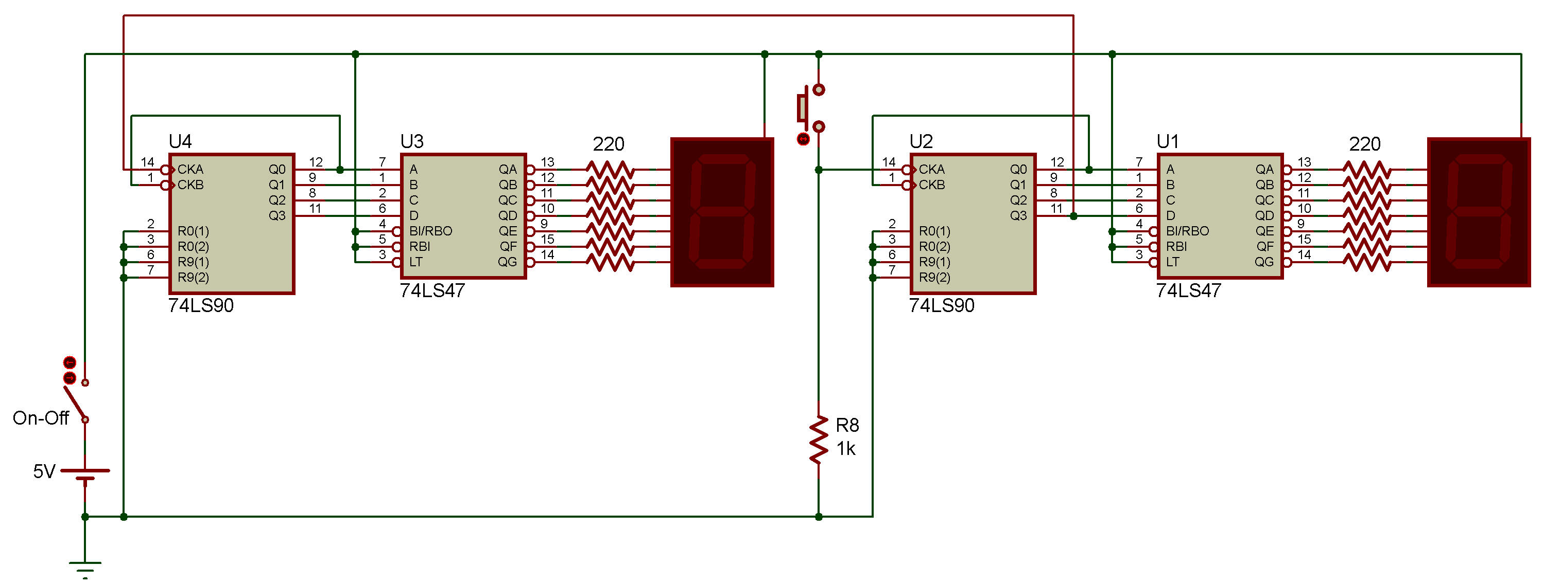
| Comment
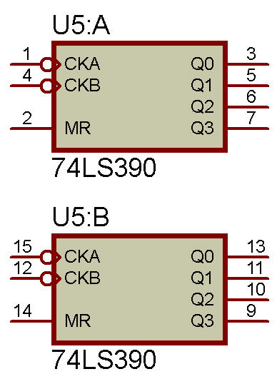
fonctionne ce compteur à affichage 7 segments à 2 chiffres ? La première partie du circuit du compteur numérique fonctionne comme précédemment, à ceci près que l’activation du bouton-poussoir incrémente l’affichage des unités. Le premier compteur BCD 74LS90, U2, compte de 0 à 9 (0000 à 1001) à chaque fermeture (front descendant) du bouton-poussoir. Cependant, lorsque la séquence de comptage atteint « 8 » (1000) sur l’affichage des unités, la broche 11 de U2, correspondant à la sortie « D », passe à l’état haut et y reste jusqu’à ce que U2 se réinitialise à zéro au 10e cycle, moment auquel la broche 11 de U2 repasse à l’état bas. Lorsque la broche de sortie 11 (broche D du circuit BCD) de U2 est connectée à l'entrée d'horloge A (CLK) 14 du compteur BCD 74LS90 U3, chaque commutation HAUT/BAS successive de la broche 11 (sortie D) de U2 incrémente l'affichage LED du second compteur pour le chiffre des dizaines. Ainsi, les deux affichages LED, placés côte à côte, comptent de 00 à 99 avant de revenir à 00 pour le comptage suivant. Ce circuit de comptage numérique très simple trouve de nombreuses applications dans les projets scolaires. Par exemple, en remplaçant le bouton-poussoir manuel par un capteur, on peut compter des objets en mouvement, des personnes, des voitures, etc. On peut également remplacer le commutateur par une minuterie 555 ou un oscillateur astable, par exemple, pour compter un nombre d'impulsions, ou comme un simple chronomètre à deux chiffres ou un chronomètre de réaction, avec ou sans virgule. Bien que le circuit de compteur à 2 chiffres décrit ci-dessus fonctionne correctement avec le compteur décimal (diviseur par 10) 74LS90, le problème est qu'il nous en faut deux, U2 et U4. Le circuit intégré TTL 74LS390 et son équivalent CMOS, le 74HC390, intègrent deux compteurs décimaux 74LS90 dans un seul boîtier et sont généralement plus économiques que l'achat de deux 74LS90. Le compteur décimal 4 bits TTL 74LS390 possède deux diviseurs internes (un diviseur par 2 et un diviseur par 5) qui peuvent être configurés pour effectuer des divisions par des multiples de « 2, 5 ou 10 » avec une sortie BCD, comme pour un seul 74LS90. Ainsi, nous pouvons remplacer les deux circuits intégrés 74LS90 (U2 et U4) du circuit précédent par un seul circuit intégré 74LS390, chaque moitié pilotant une des LED d'affichage, comme illustré. |
So how does
this 2-digit 7-segment display counter work. The first half of the digital counter circuit works the same as before except that the activation of the pushbutton increments the “one’s” (also called “units”) LED display. The first 74LS90 BCD counter, U2 counts upwards from 0 to 9 (0000 to 1001) on each closing (trailing-edge) of pushbutton . However, when the counting sequence reaches “8” (1000) on the one’s display, pin-11 of U2 corresponding to output “D” goes “HIGH” and stays HIGH until U2 resets itself back to zero on the 10th count at which time pin-11 of U2 goes “LOW” again. As output pin-11 (BCD pin D) of U2 is connected to the clock A (CLK ) input pin-14 of the second 74LS90 BCD counter U3, each sucessive HIGH/LOW switching action of pin-11 (output D) of U2 increments the second LED display for the ten’s digit. Thus causing the two LED displays when placed side-by-side to count upwards from 00 to 99 before restting back to 00 again for the next count. This very simple digital counting circuit has many different school project applications. For example, if we can replace the manually operated pushbutton switch with a sensor to count moving objects, or people, or cars, etc. Or even replacing SW with a 555 timer or astable oscillator circuit for example, it could be used to count a number of pulses, or as a simple 2-digit timer or reaction timer circuit with or without the decimal point. While the above 2-digit counter circuit works well with the 74LS90 decade (divide-by-ten) counter, the problem is we need two of them, U2 and U4. The TTL 74LS390 and its CMOS equivalent, the 74HC390, contain two 74LS90 decade counters within a single IC package and in most cases is more cost effective than buying two 74LS90’s. The TTL 74LS390 4-bit decade counter has two divide-by-two and divide-by-five counters internally which can be configured as a divide-by-multiples of “2, 5 or 10” with a BCD output the same as for the single 74LS90. Thus we can replace the two 74LS90 IC’s U2 and U4 in the previous circuit with one single 74LS390 IC with each half of the IC driving one of the LED displays as shown. |
 |
|
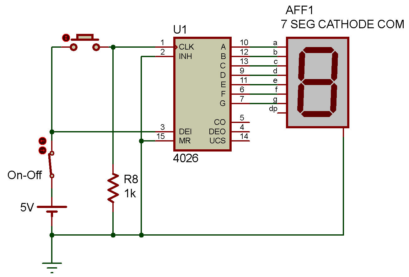
| Pour
simplifier le circuit on peut utiliser un 4026 qui est un compteur et un
décodeur 7 segments (Common Cathode (CC)). Avec un 4029 on a pas besoin de résistances pour le 7-segments. |
To simplify
the circuit, we can use a 4026 which is a counter and a 7-segment
decoder
(Common Cathode (CC)). With a 4029 you don't need resistors for the 7-segment. |
 |
|
![]()