Logic NOR Circuit (Part 2)
Here is another project to demonstrate the NOR logic circuit (many different types of circuit configurations, can accomplish the same function).
A NOR circuit is a combination of an OR gate ("gate" is another word used for a logic circuit) and an inversion gate. You can think of it as an inverse OR or as a NOT OR (or even just keep in mind the word combination "neither/nor" — neither one input nor the other will give an output).
This NOR circuit works as follows:
When there is no input (no light falling on the Solar or CdS Cell), there will be an output (the Lamp will light).
However, neither one input NOR the other can produce an output (neither can both inputs). Confusing? Try it.
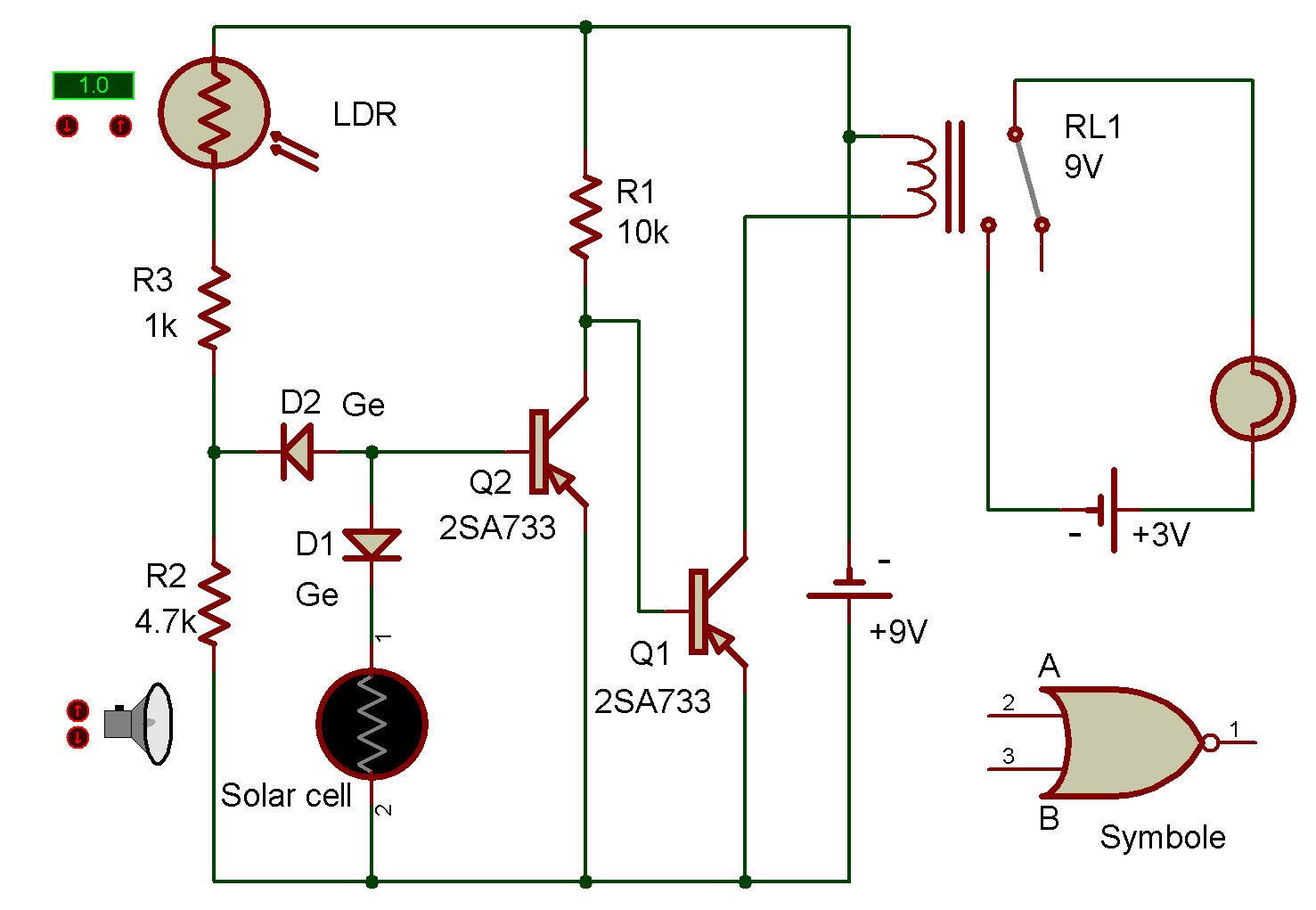
This demonstration circuit works as follows:
1. In darkness the Lamp goes ON.
2. If bright light strikes either the Solar Cell or CdS Cell or both, the Lamp goes OUT.
A Truth Table of this action is as follows:
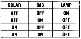
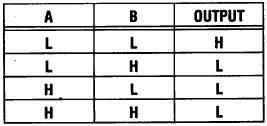
Expressing it as : A=Solar Cell; B=CdS Cell; H = 0N; L=OFF; OUTPUT=Lamp.
Either the CdS or the Solar Cell turns ON the 2SA(2) and turn OFF the 2SA(1), when the light hits it.
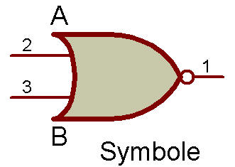
Now you will want to compare this circuit with the NAND circuit of project Logic "NAND" with LED Display. The symbol for the NOR circuit is shown next to the Schematic. It is the same as an OR symbol, with a small circle added at the output (this means the main symbol function is inverted).

![]()