Logic "NAND" with LED Display
The purpose of this project is to study a logic NAND circuit. A NAND logic function is an inverted AND function. That is, the output conditions are opposite to those of the AND function. The NAND Truth Table is as follows:
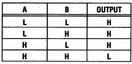
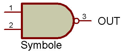
Expressd in words, both A and B must be high for the output to be low. The logic symbol is like the AND symbol, but with the addition of a circle at the output to indicate inversion.
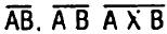
This function may also be written
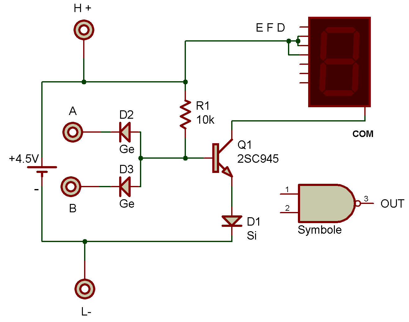
Circuit operation is as follows:
Whenever either one or both of the inputs are conected to L (terminal L-), the forward voltage drop of either germanium (Ge) Diode keeps the NPN Transistor from turning ON. The LED cannot receive any current at this time, and remains dark.
Whenever both inputs are connected to H (H+), both Diodes are reversed-biased across the 10K Resistor and perform no function. The 10K biases the NPN Transistor ON, so that current can flow between emitter and collector to light the LED segments.
As with project Logic "AND" with LED Display, this circuit also provides a high (H) input to the input terminals when they are not connected to the low (L) terminal. In contrast to project "AND" with LED Display, this circuit has a (+) for high (project "AND" with LED Display used (-) for a high).
Either metnod can be used. When the more positive voltage is used as the high, the logic is called "positive logic", when the more negative is used as the high, it is called "negative logic".
Note:
Did you catch the trick we played on you? High output in this case is no LED display, and low output causes a letter L display on the LED. There are different forms of output, don't let electronic circuitry trip you up (check it over carefully).

![]()