Window comparator LM324
74HC00
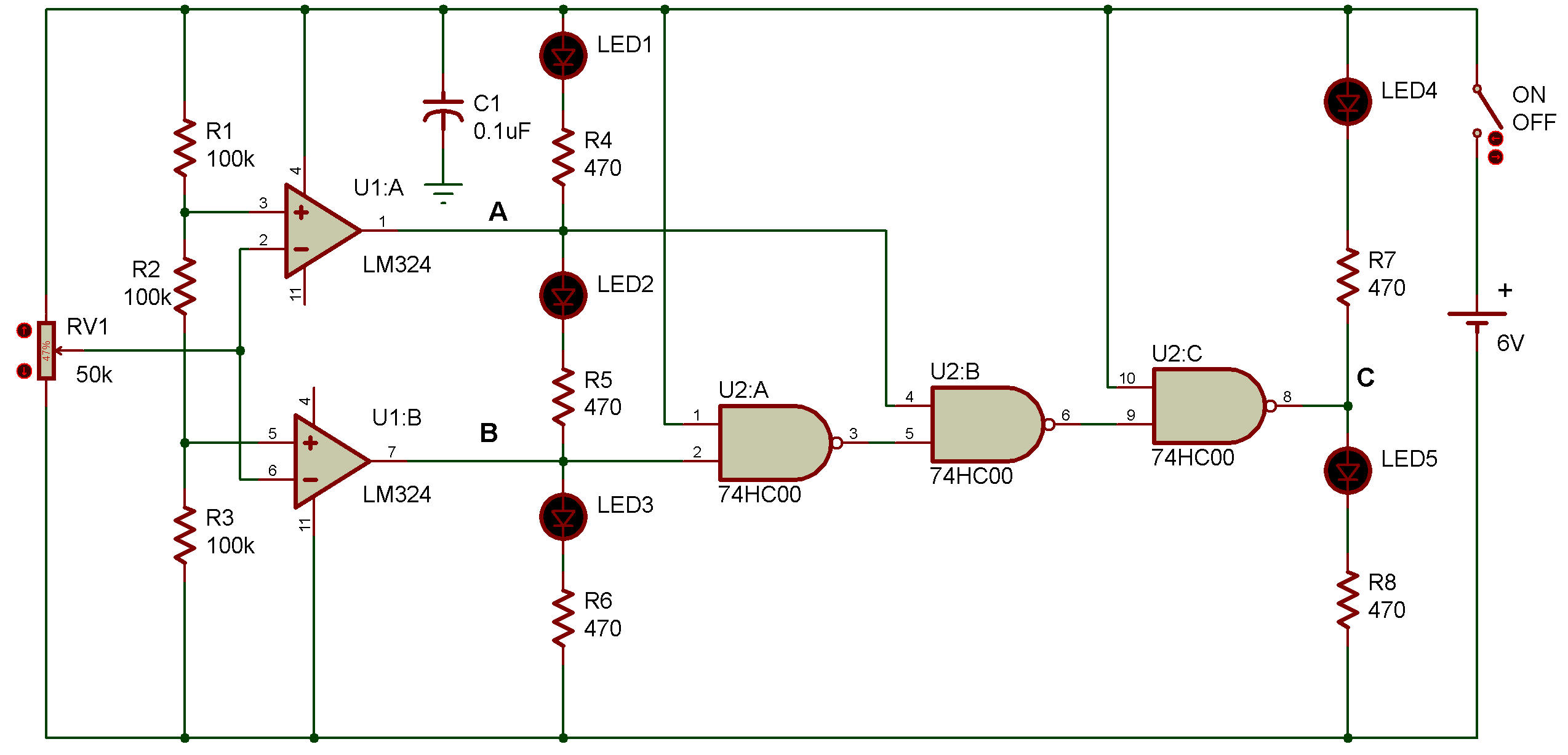
Using two op amplifiers, we can build a window comparator that generates an output only when the input voltage is held between two reference voltages. The schematic shows you see that LED 2 and LED 5 stay ON while the window comparator keeps generating its output.
When you finish wiring, turn the control volume fully counterclockwise and turn power ON. You'll see LED 3 and LED 4 light up.
Now, rotate the control volume fully clockwise and see what happens. LED 1 and LED 4 light up this time.
Now set the control volume around the 12 o'clock position and rotate it slowly to the right and left, and you'll notice LED 2 and LED 5 light up at some point. At this time, the input voltage is between the two reference voltages (Vref = 2V, Vref2 = 4V).
Figure 1 helps you obtain a clear understanding of the function of the window comparator.
| Vi (V) |
Lower | Middle | Upper | Comparator's signal | ||||
| LED 3 | B | LED 2 | A | LED 1 | LED 4 | LED 5 | C | |
| 6-4 | • | L | • | L | ° | ° | • | L |
| 4-2 | • | L | ° | H | • | • | ° | H |
| 2-0 | ° | H | • | H | • | ° | • | L |
| LED OFF :
• LED ON : ° |
||||||||

![]()