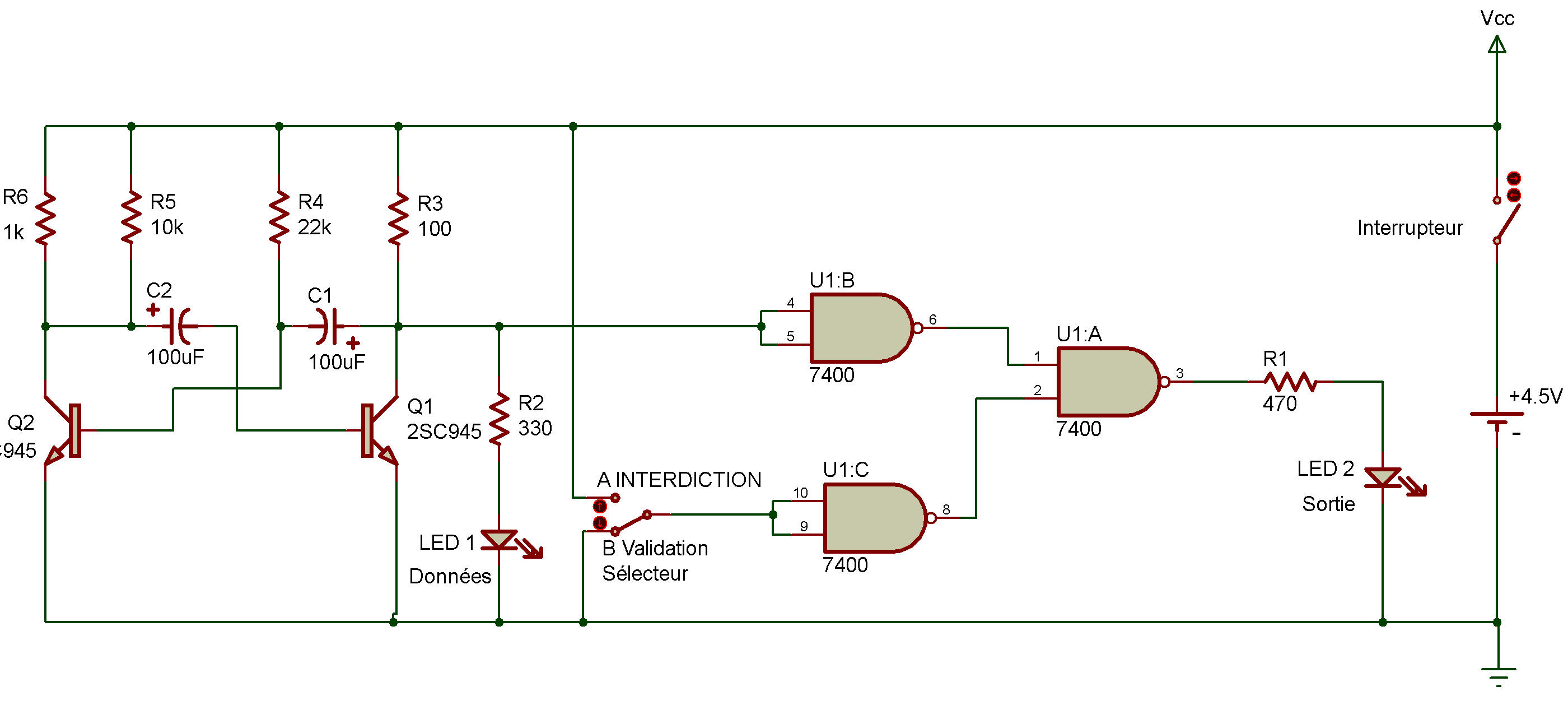
TTL OR enable circuit
7400
Did you ever figure out how to make up an enable circuit using an OR gate?
If you did, here's a chance to check your ideas against an OR enable circuit we've cooked up. Like our last two Projects, a multivibrator "feeds" input to the OR gate.
You can see the output of the OR gate when you look at LED 1, it'll flash on and off according to the output of the multivibrator. Can you tell what will happen once the multivibrator's input is applied to the OR gate by looking at the schematic?
Give it a shot before building the Project. As you build this circuit, try setting the Select Switch to A instead of B like we did for the last two Projects. After you finish the wiring connections, turn the power ON. What does LED 1 do?
And what is LED 2 doing?
Now set the Select Switch to B. What happens to LED 1 and LED 2 now?
You say that in this circuit setting the Select Switch to A blocks the flow of data from LED 1 to LED 2 (this is called the inhibit status).
But when the Select Switch is at B, data can flow from LED 1 to LED 2. This is called the enable status.
This circuit works like it does because a NAND gate can give an output of 1 only if both inputs are 0. When you set the Select Switch to A, the inputs to one NAND are at 1. The output is 0, and this supplies one of the inputs of the NAND gate controlling LED 2.
This 0 input never changes as long as the Select Switch is left at A. But when the Select Switch is set to B, both inputs become 0 and the output becomes 1. This means one of the inputs to the NAND controlling LED 1 becomes 1 all the time, and LED 2 can now blink on and off depending on whether the other input is 0 or 1. (Now there was nothing difficult about that, was there?)

![]()