TTL j-k flip-flop 1
7400, 7476
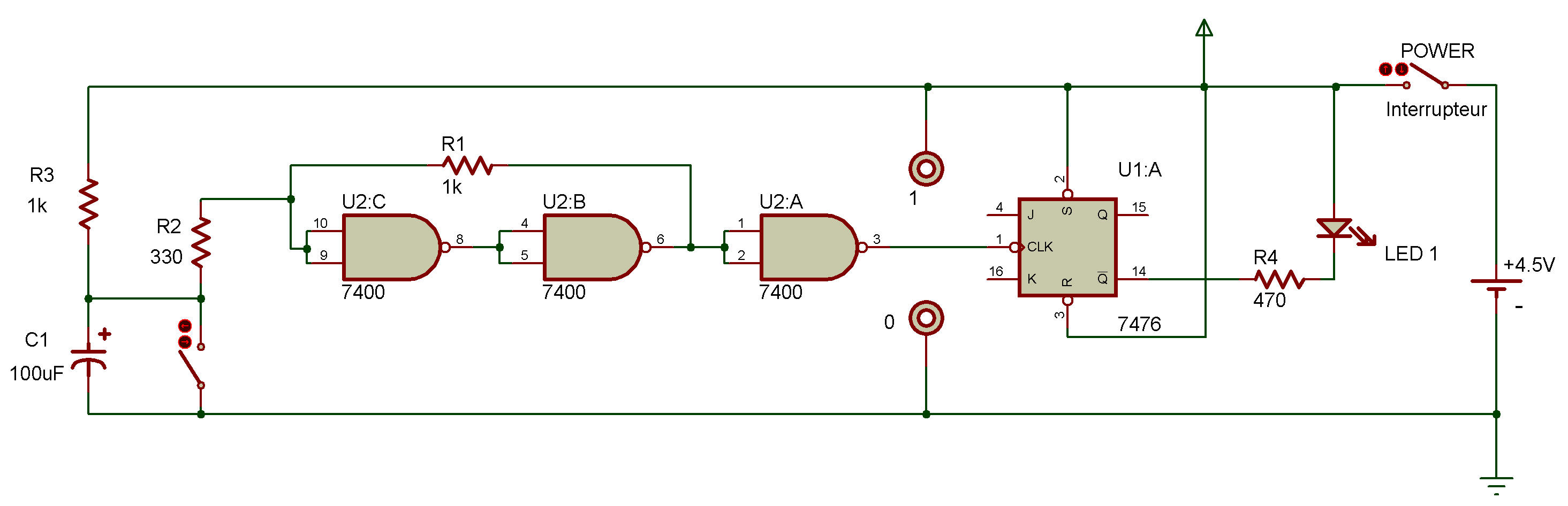
In Project J-k toggle flip-flop you saw how a flip-flop circuit can be "toggled" so that we can have additional control over it TTL circuits can be used to provide this added control, as this Project will demonstrate.
You can see by the schematic that you'll provide the clock signal for, this circuit each time you press the Key.
The signals for the J and K inputs are provided by touching the long wires from terminals K and J to other terminals.
After you build this Project, putpower ON and press the Key a few times, You'll see LED 1 go on and off.
Now take the long wire from terminal J and connect it to terminal 0, Press the Key a few times. What happens to LED 1?
Disconnect the long wire from terminal 0 and reconnect it to terminal 1 and press the Key again. Is there any difference in what LED 1 does?
Take the long wire from terminal K and connect it to terminal 0. Press the Key several times. What does LED 1 do now?
Disconnect the long wire from terminal 0 and reconnect it to terminal 1 and press the Key again. What happens to LED 1?
As you may have figured out, if both the J and K inputs axe 1, the flip-flop will set and reset each time you press the Key (which inputs a clock signal), This means LED 1 will go on and off.
But if you connect the long wire from terminal J to terminal 0, this makes the J input 0 and the K input 1. This means LED 1 will go out when the flip-flop receives a clock signal and will stay out.
When the long wire from terminal K is connected to terminal 0, the J input is 1 while the K input is 0. This means LED 1 lights with a clock signal and stays lit.
Time to put on your thinking cap, can you thinjk of some of the interesting things that could be done of you used different types of multivibrator circuits for the clock, J and K inputs? Try whipping up some circuits to see if you're right.

![]()