TTL AND gate with three inputs
7400
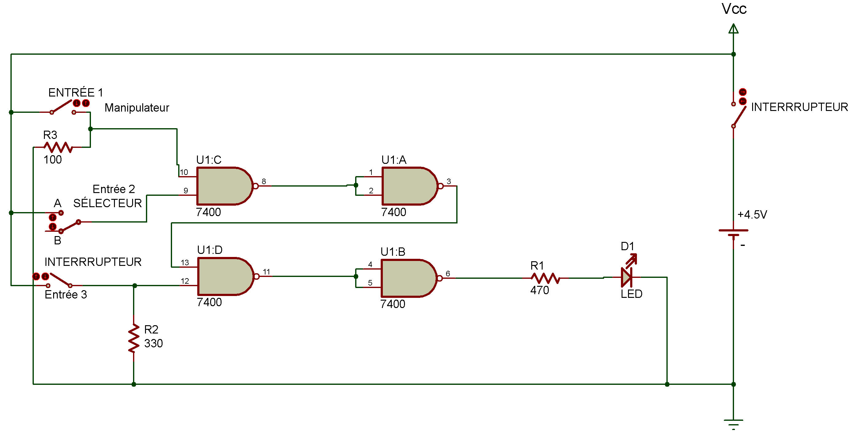
Even though we've been playing with digital circuits that have just two inputs, that doesn't mean we can't have more than two inputs. Here's a TTL AND gate that has three inputs. Try and figure out how 3 inputs produce a 1 output from the schematic.
You'll notice that we're doing things a bit differently this time, the power switch isn't used to turn this Project on or off, Instead, it's used to input a 0 or 1 signal.
You know by now how AND gates work, so we won't go into detail here. But can you look at the schematic and figure out the setting for the two switches and Key so that you get a 1 output?
Try it and then see if you were right.
Here's how this circuit works:
the Key and Select Switch are connected to one NAND. When they are both 1, the NAND outputs a 0. This 0 then makes up the input of another NAND, causing its output to become 1. This 1 output then goes to another NAND gate (see it on the schematic?).
There it makes up one input, along with the input from the power switch making up the other. When these are both 1. the NAND's output goes to 0. This output is used for both inputs of the second NAND, causing it to become 1 and the LED lights.
Seems simple, doesn't it? Believe it or not, even complex computers operate by using the same basic principles we're using with the digital circuits in this section.

![]()