DTL OR gate
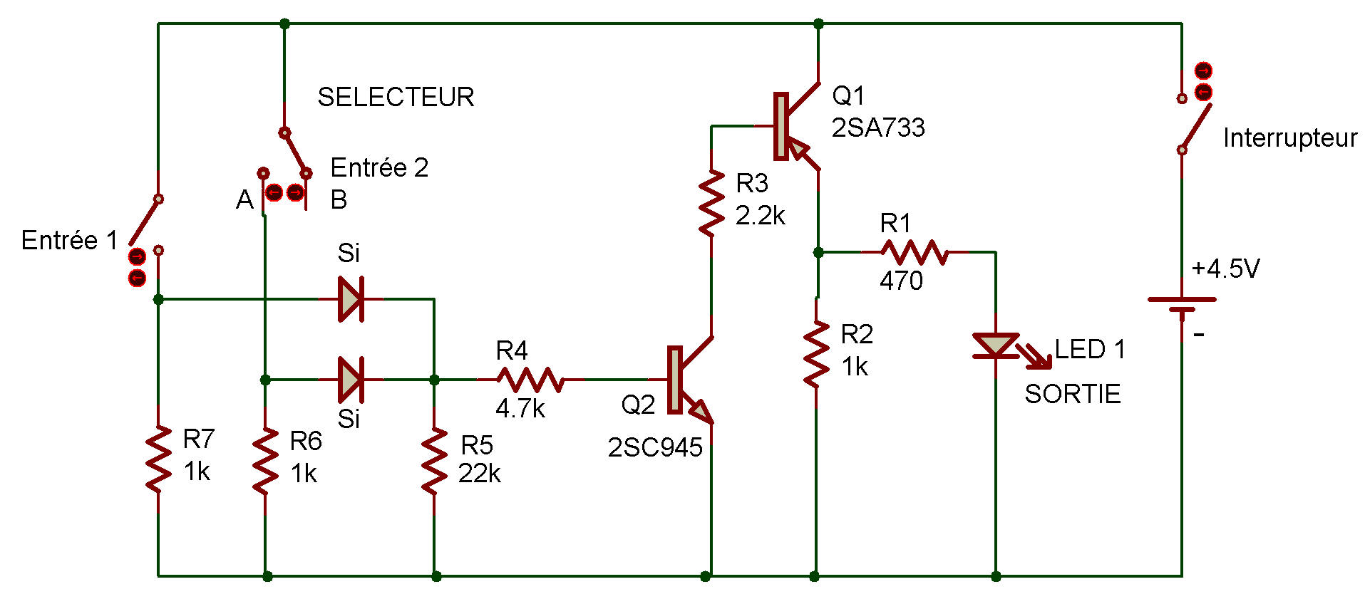
"DTL" stands for diode-Transistor logic, which is a digital circuit using diodes and transistors. As you can see from the schematic for this Project other components (such as resistors) are used but the circuits operation depends upon the diodes and transistors.
Before you start building this Project, do you think there's any difference between how this DTL OR gate works and how the RTL OR gate gate worked?
Make a mental note and then start making the wiring connections. Be sure to set the Select Switch to B during the wiring. After wiring, put the power ON. Press the Key and see what happens to LED 1.
Now release the Key and set the Select Switch to A. What happens now?
Leave the Select Switch at A and press the Key. Is there any change?
You discovered this circuit behaves like the other OR gates you've built. You can see how this circuits works by looking at the schematic.
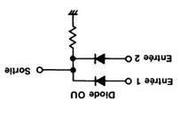
Pressing the Key or setting the Select Switch to A allows current to flow to the base of the 2SC transistor, which then enables the 2SA Transistor to operate. Compare your circuit with the one below (we've printed it upside-down... don't peek until you've drawn your own circuit.)
It's also possible to make an OR gate out of just two diodes and a resistor. Can you figure out how? (If you need some clues, try looking back at Projects Meet the Diode, Voltage Drop and Voltage Regulator in Diode section) Be sure to draw schematics for any circuits you come up with.

![]()