C-MOS NOR gate
74HC00
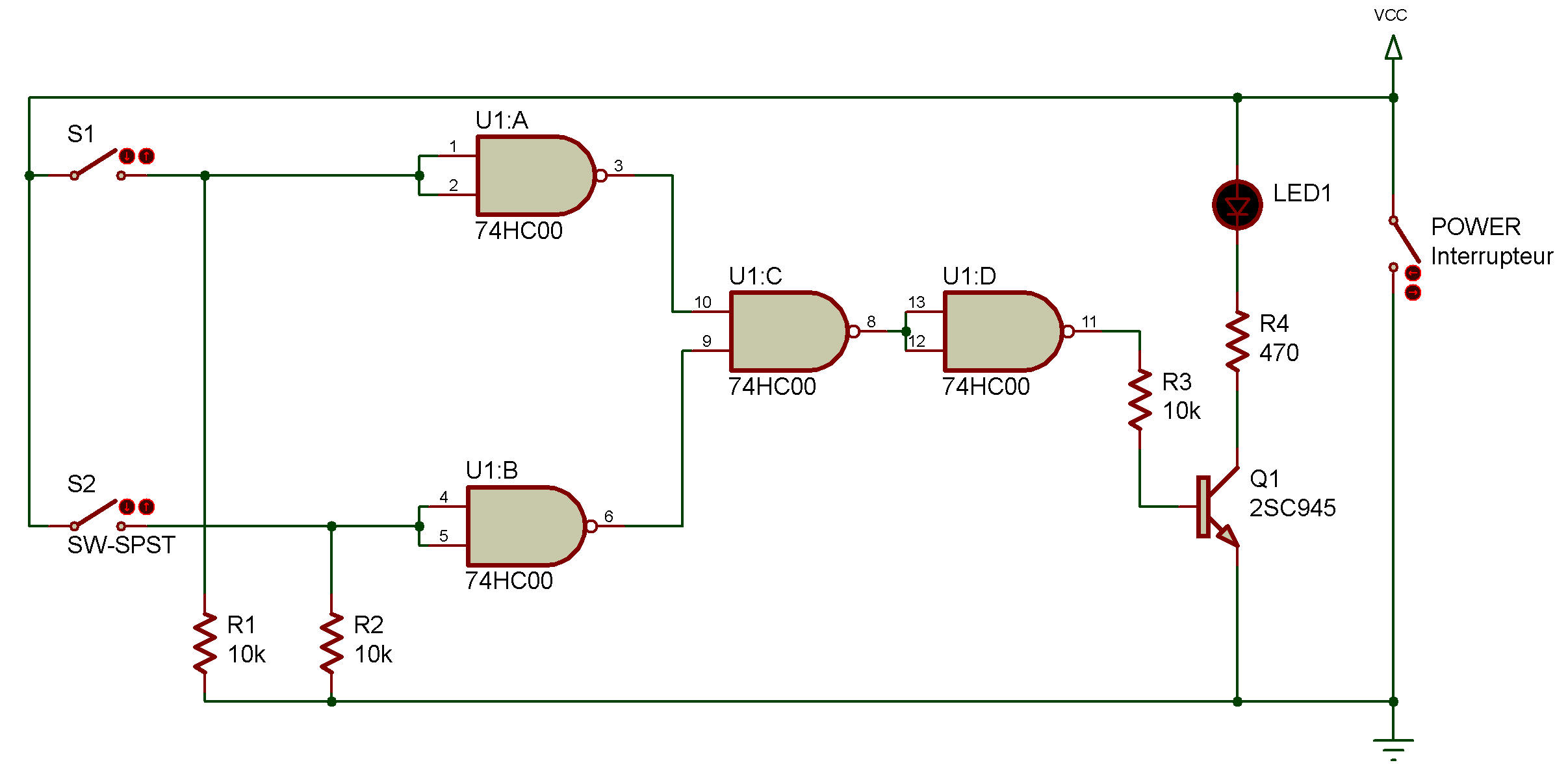
Try the same thing you've been doing with the past few projects... trace the "logic flow" of this circuit! Start with a 0 or 1 input and see how this circuit arrives at a 0 or 1 output. Give it a good try... and don't peek at the answer.
Whit This Quad 2-input NOR Gate ICs you can organize the NOR Gate by using NAND Gate.
When you finish the wiring connections, turn power ON and press S1. Is there any change in LED 1 ?
Release S1 and press S2. What happens to LED 1 now?
While keep pressing S2, press S1 ... does anything different happen?
As you just saw, this project behaves just like other NOR gates we've built. And it does so because... ... pressing S1 or S2 inputs a signal of 1.
This is used for both inputs of the NANDs marked a or b. a and b have an output of 0 with an input of 1, and their outputs are used for the inputs to the NAND marked c.
As long as one or both inputs are 0, the NAND marked c has an output of 1. This 1 output is used for the inputs of the next NAND, causing an output of 0 .... and goes out the LED. Don't believe us?
Try putting a "0" or "1" on the schematic - see how it changes.

![]()