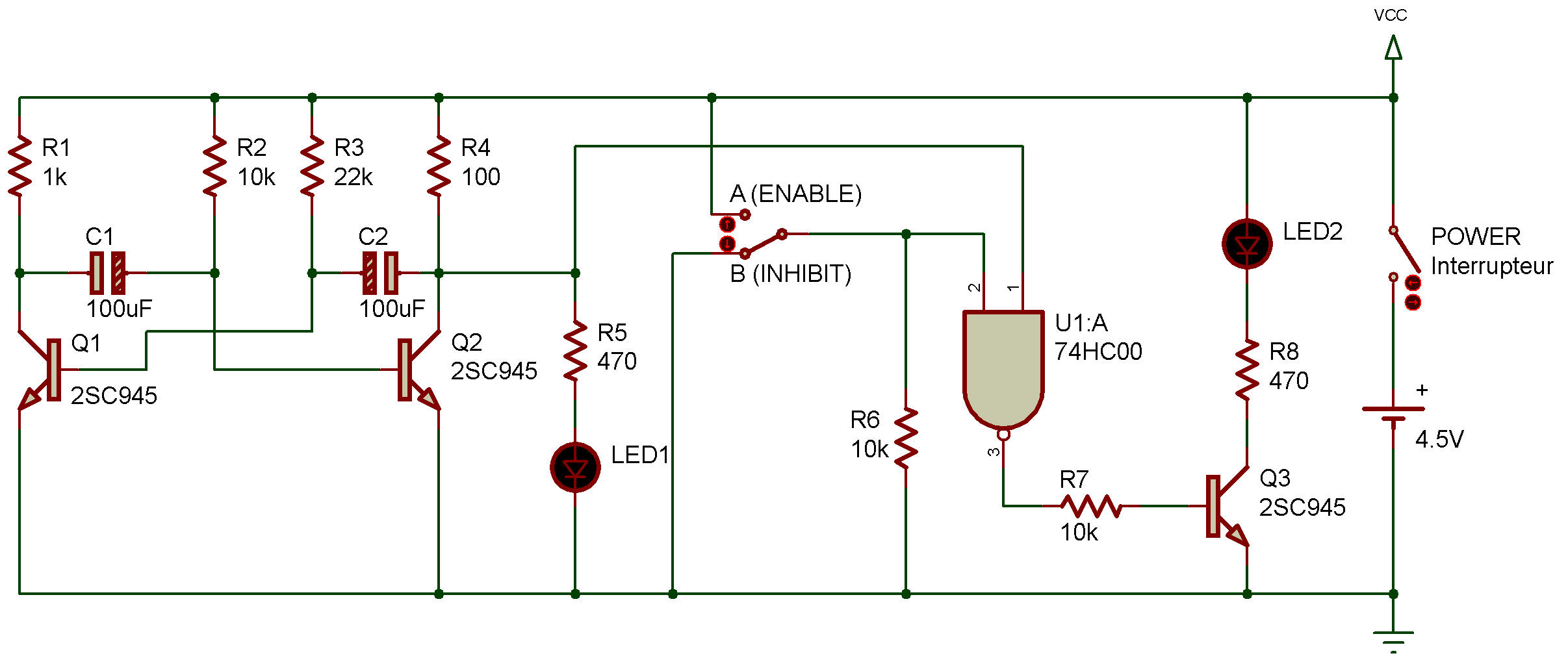
C-MOS NAND enable circuit
74HC00
NAND gates can also be "electronic sentries." If you don't want a signal to pass, a NAND gate can make sure it doesn't. We call this project a "NAND enable circuit" because that what the NAND gate does - it enables signals to pass through a channel.
The two LEDs let you see whether or not the signal shown at LED 1 is allowed to pass to LED 2. You probably recognized one circuit in the schematic right away - the multivibrator. You can see the output of the multivibrator by watching LED 1. You'll also notice that the multivibrator provides one of the inputs to the NAND gate.
What do you suppose happens when the select switch is up or down?
Be sure to make some mental notes because we're about to find out.
As you build this circuit, set the select switch down, and look at LEDs 1 and 2. You'll see LED 1 "blink" to indicate the output of the multivibrator. But look at LED 2. You'll see that it stays lit all the time, indicating that something's preventing the signal at LED 1 from reaching LED 2.
Now set the select switch up and observe LED 2. What is happening?
Is the same thing happening to both LED 1 and LED 2?
You can see that LED 1 and LED 2 "take turns" going on and off. This is because we set one input of the NAND to 1 when we set the select switch up.
The multivibrator sends 0 and 1 signals to the other input. When the signal is 1, LED 1 lights but both input signals to the NAND are then 1. That means the NAND's output is 0, and LED 2 goes out.
Then one of the inputs to the NAND becomes 0, its output goes to 1 and LED 2 lights. (Now be honest - did you figure all that out before building the circuit?? We hope so.)
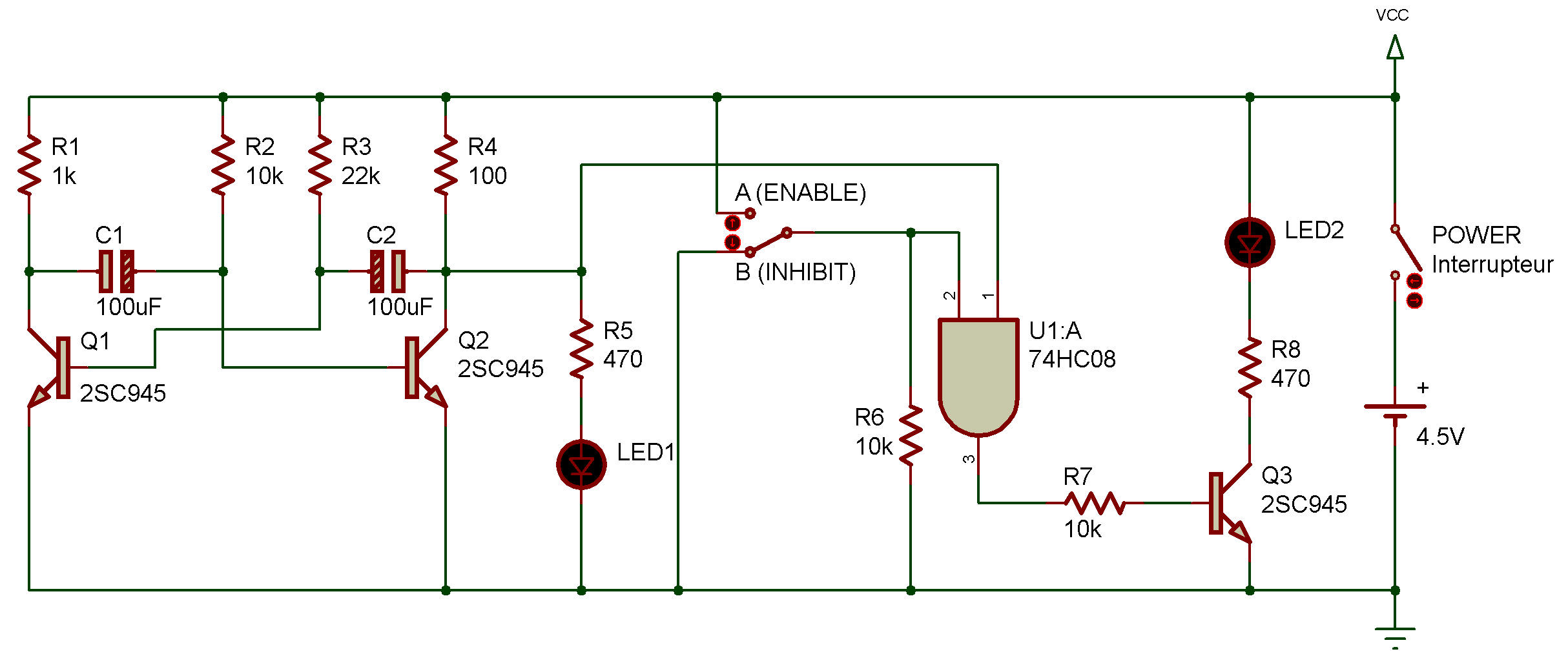
C-MOS AND enable circuit

![]()