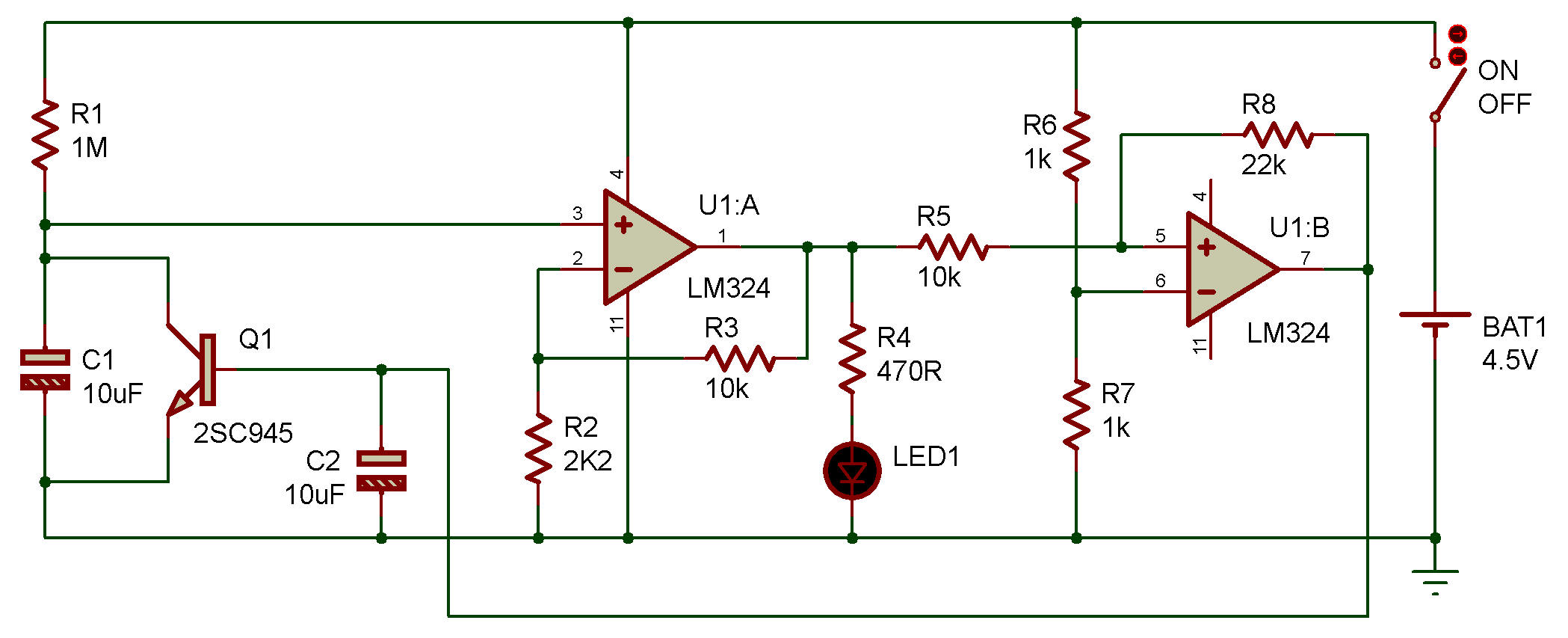
Sawtooth wave oscillator, LM324
In this project, you're going to make a sawtooth wave oscillating circuit.
Here, however, you'll use an OP amplifier. Imagine the sawtooth wave by looking at the way the LED changes in brightness.
When you finish wiring, turn power ON. LED 1, which was dark at the beginning, becomes gradually but linearly brighter and suddenly back to darkness. This cycle is repeated.
Sawtooth waveforms find many practical applications. The most important are as sweep voltages of oscilloscopes, and the deflection of the electron beam in television picture tubes.
R1 and C1 form an integrating circuit. The linear rising portion of the integrated waveform is used as our sawtooth wave. C1 becomes charged after power is turned ON.
The voltage across C1 (sawtooth wave voltage) is amplified by U1 A. When the output wave from U1A exceeds the voltage (V3/2) at the (-) terminal of the comparator U1B, the output of U1B changes to H, Q1 turns ON, and C1 becomes rapidly discharged through Q1.
When C1 has been discharged, the output of U1B returns to L, and Q1 turns OFF. This process is repeated to oscillate the sawtooth wave.

![]()