Principles of piping drawings
Introduction
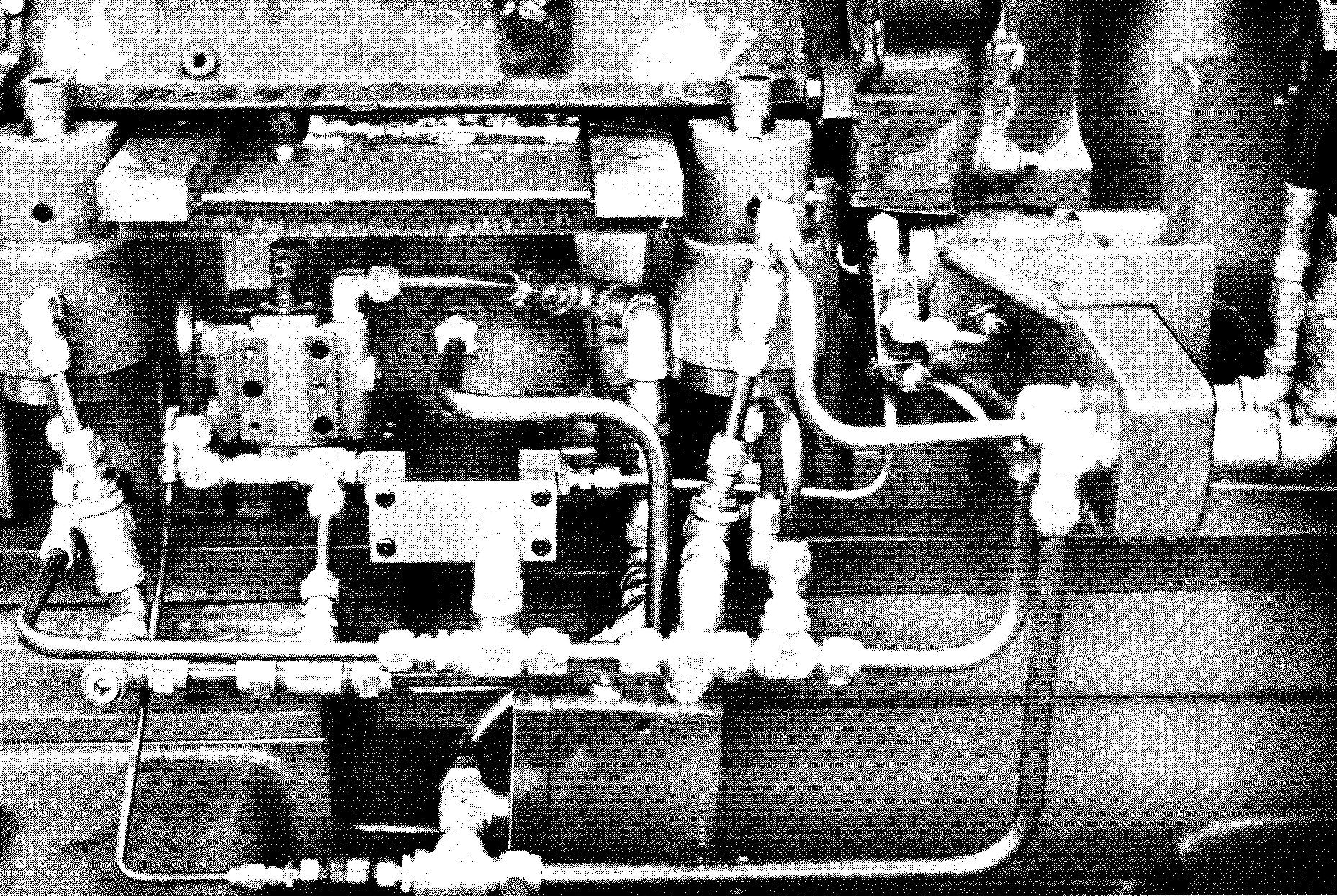
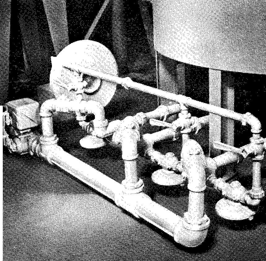
More and more industrial machines of today are connected with a wide variety of pipe and pipe fittings for drainage and for supplying gas, steam, oil, coolants and cutting oils, water, air, and minerals. Figure 20-1 shows two typical industrial piping systems.
fig. 20-1. piping systems in industrial use
Drawings for systems of this kind are prepared to supply the pipe fitter with various information on the kinds and sizes of the parts required for the installation. While drawings of most piping systems are usually not drawn to an accurate scale, each part must be properly shown to convey the intended use and assembly of the parts.
A machine draftsman who has a knowledge of pipe and pipe fittings and the best methods of representing them can hold a responsible position in his company. In the design of machines and structures requiring piping installations, the engineer generally specifies precisely what is required.
The draftsman prepares the final drawings according to the data supplied to him. He should have a working knowledge of how to properly represent, dimension, and specify pipe fittings and threads. The engineer depends upon the draftsman to check on such items as the possible use of available standard parts and clearances or interferences of one part to another.
The draftsman should be able to read and understand handbooks, commercial catalogs, American Standards Association manuals, and company standards books relating to piping drawing. Reference sources such as these are commonly available in most drafting departments.
Kinds of pipe
Cast iron pipe is frequently installed underground to carry gas, water, or sewage. It is also used for low pressure steam systems. Cast iron piping is somewhat brittle and will not withstand sudden strain or shock. It is highly resistant to corrosion (the gradual wearing away of metals by the action of chemicals).
Water and gas pipes are available in sizes ranging from 3 to 60 inches ID (inside diameter) and in 12 foot lengths. Soil pipe for sewage systems is available in sizes from 2 to 15 inches ID and in 5 foot lengths.
Steel pipe and wrought iron pipe are used to carry steam, oil, and gas. Steel pipe is commonly selected to carry liquids and gases under high pressure and temperatures. Steel pipe is available as black pipe or galvanized pipe.
Galvanized pipe is made by dipping ordinary steel pipe into a bath of molten zinc. The zinc coating prevents rusting and is often used for pipes which carry drinking water.
Small diameters of steel and wrought iron pipe are available in lengths of 40 feet. Wrought iron is more costly than steel but is considered to be a more suitable material for withstanding corrosion.
Brass pipe and copper pipe are considered ideal for withstanding corrosion, but each is more expensive than steel or wrought iron pipe. Designers avoid using brass or copper pipe for conditions requiring high temperatures or repeated stress. Brass and copper pipe are available in lengths of 12 feet.
Copper tubing is often used in building construction for plumbing or heating. It may be readily bent and is particularly useful for systems with turns which require changing the direction of pipe lines.
Copper tubing is available in diameters of approximately 1/8 inch to 12 inches ID. Soft copper tubing is available in coils of 60 feet. Hard temper copper tubing is available in straight lengths of 20 feet. Unlike soft copper tubing, it cannot be coiled.
Lead and lead lined pipe are often used in chemical systems where the pipe is subject to the action of acids.
Plastic pipe is being increasingly used for piping systems. It is extremely flexible and may be easily installed. It is not recommended for use under extreme heat or pressure. It is, however, considered suitable for carrying acids and chemical substances. Plastic pipe may be installed underground without harmful effects.
Sizes of pipe
When the designer specifies a particular kind of pipe needed for an installation, the draftsman must consult appropriate piping tables for the dimensions. For pipe up to 12 inches ID, the size is designated by the inside diameter. Pipe measuring over 12 inches is measured and specified by the OD (outside diameter).
Two terms are important in designating pipe size: the nominal diameter and the actual diameter. Both terms are used to denote the size of the hole diameter.
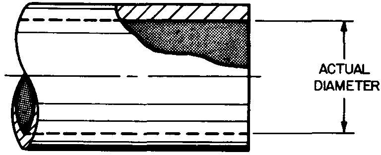
The nominal diameter designates the approximate size of the hole. The nominal diameter is always less than the actual diameter. The actual diameter designates the size the pipe actually measures, as shown in Fig. 20-2.
fig. 20-2. pipe diameters
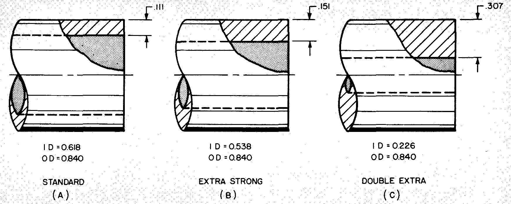
The wall thickness is the distance measured along one side, or OD — ID -=- 2. Table 68 lists the available sizes of welded wrought iron pipe according to three weights: standard, extra strong, and double extra-strong. All three weights for any given nominal size of pipe have the same outside diameter, but have a different size hole, or ID.
Identical fittings can be used, since the OD is the same for each weight. In Fig. 20-3, a 1/2 inch (nominal) steel pipe is used to illustrate the comparison of sizes.
fig. 20-3. comparison of pipe dimensions
The ASA {American Standards Association) system designates pipe by either the nominal size and the wall thickness or the nominal size and the weight per foot.
All technical information dealing with the actual specifications of the piping system, such as the strength, temperature limits, pressure requirements, sizes, material, and types of pipe and fittings, is usually supplied to the draftsman by the designer.
Pipe fittings
Parts which are connected to pipe are called pipe fittings. Making up is a term which is used to describe the process of joining the fittings to pipe.
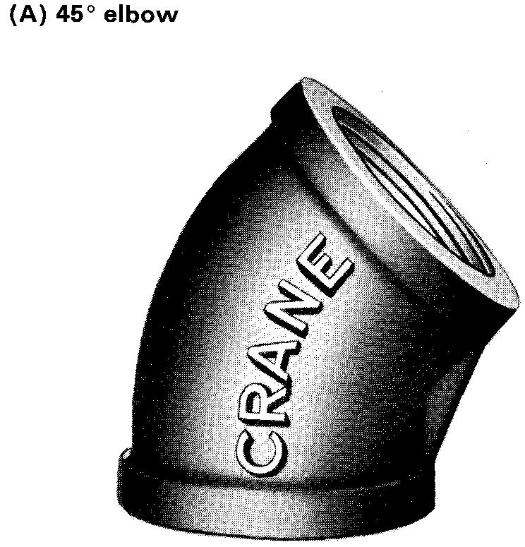
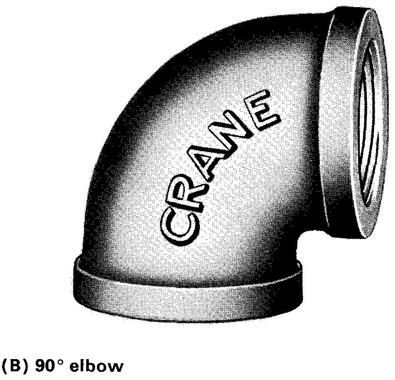
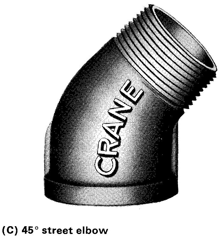
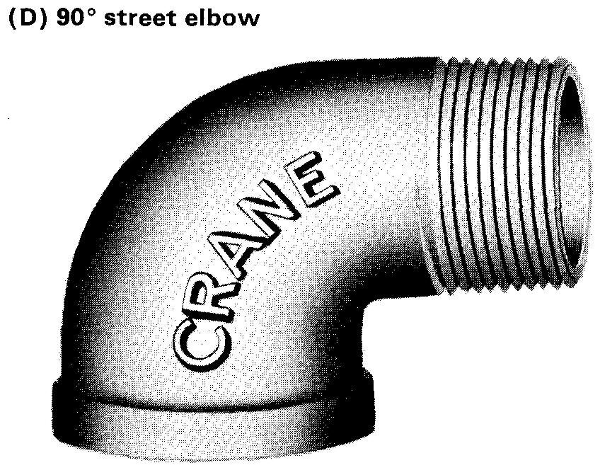
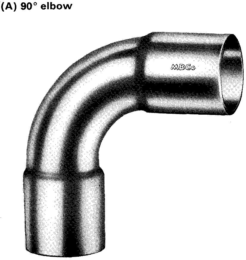
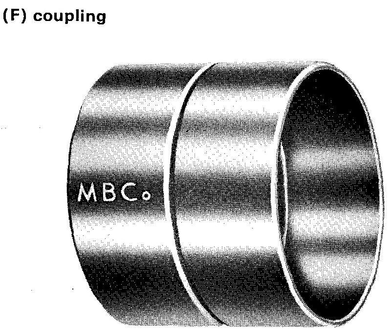
Pipe fittings include elbows, tees, crosses, couplings, nipples, unions, flanges, and so on. Fittings may be connected to piping by using threads or by soldering or welding. Special flanged joints which are assembled by bolts are also used.
Screwed or threaded fittings, shown in Fig. 20-4, are joined to the piping by simply screwing the threaded parts together.
fig. 20-4. Screwed or threaded fittings
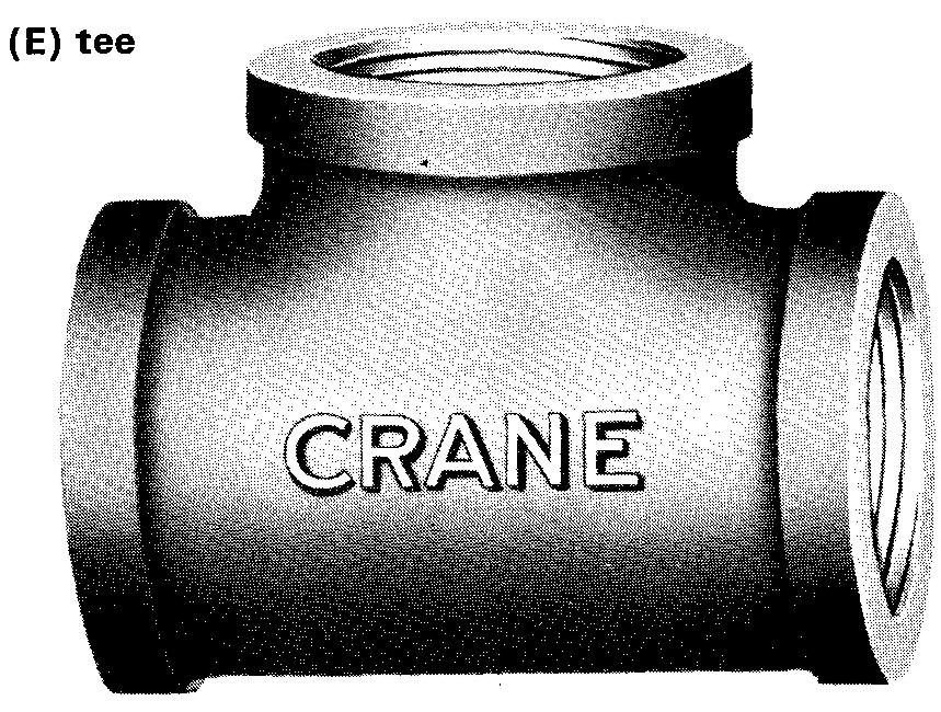
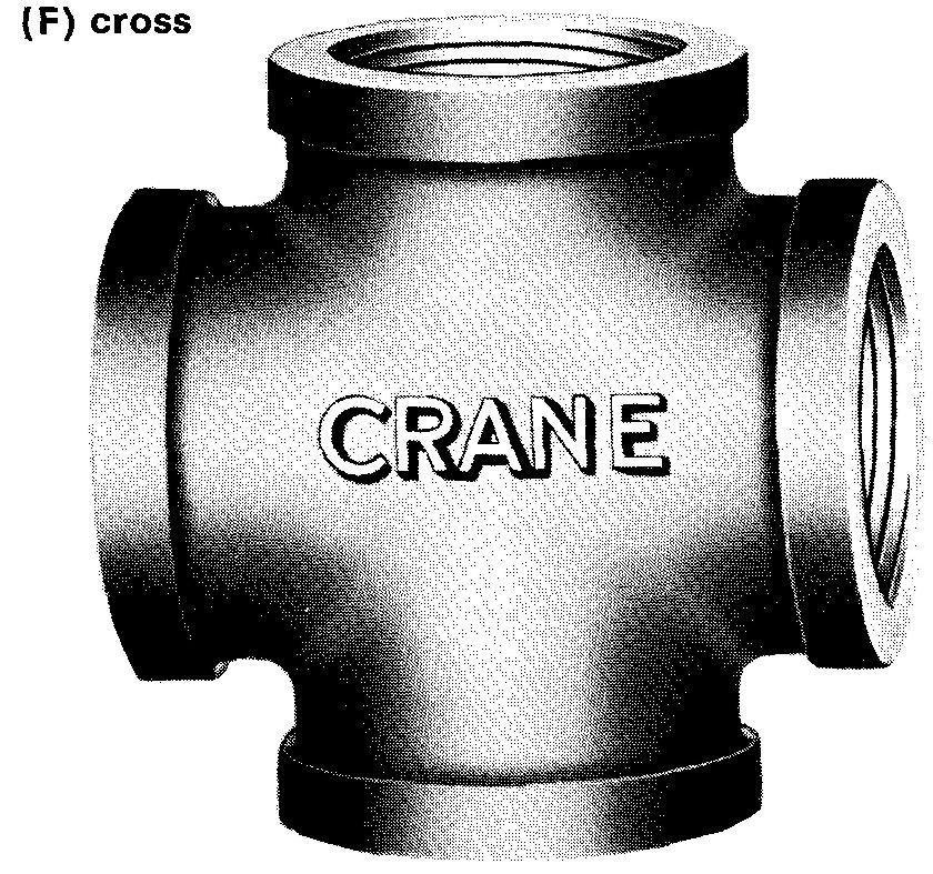
Steel, cast iron, malleable iron, bronze, and brass piping are materials commonly used for screwed fittings.
Screwed fittings are generally used in small piping systems for plumbing and heating in buildings and homes. Screwed fittings are usually restricted to pipe sizes of 2-1/2 inches or less, although piping larger than this may be used in special cases.
Pipe compound (a mixture of lead and oil) is usually applied to the pipe thread before it is screwed into the fitting. Compound is used to lubricate and to make a tight seal between the mating threads of the pipe.
Soldered fittings, shown in Fig. 20-5, are used frequently for plumbing and heating in house and building construction. Fittings for copper pipe and tubing are usually joined by soldering.
fig. 20-5. Soldered fittings
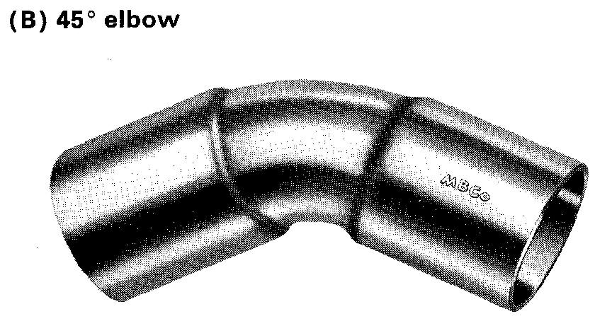
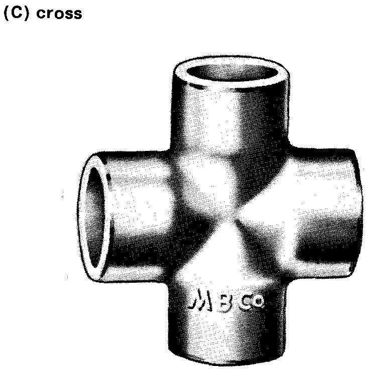
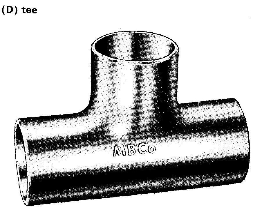
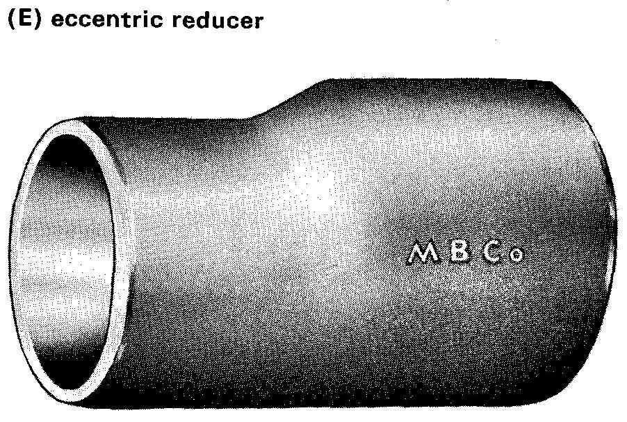
Welded fittings, shown in Fig. 20-6, are used extensively for joining small groups of parts prior to shipment or for a quick assembly on the job.
fig. 20-6. Butt welded fittings
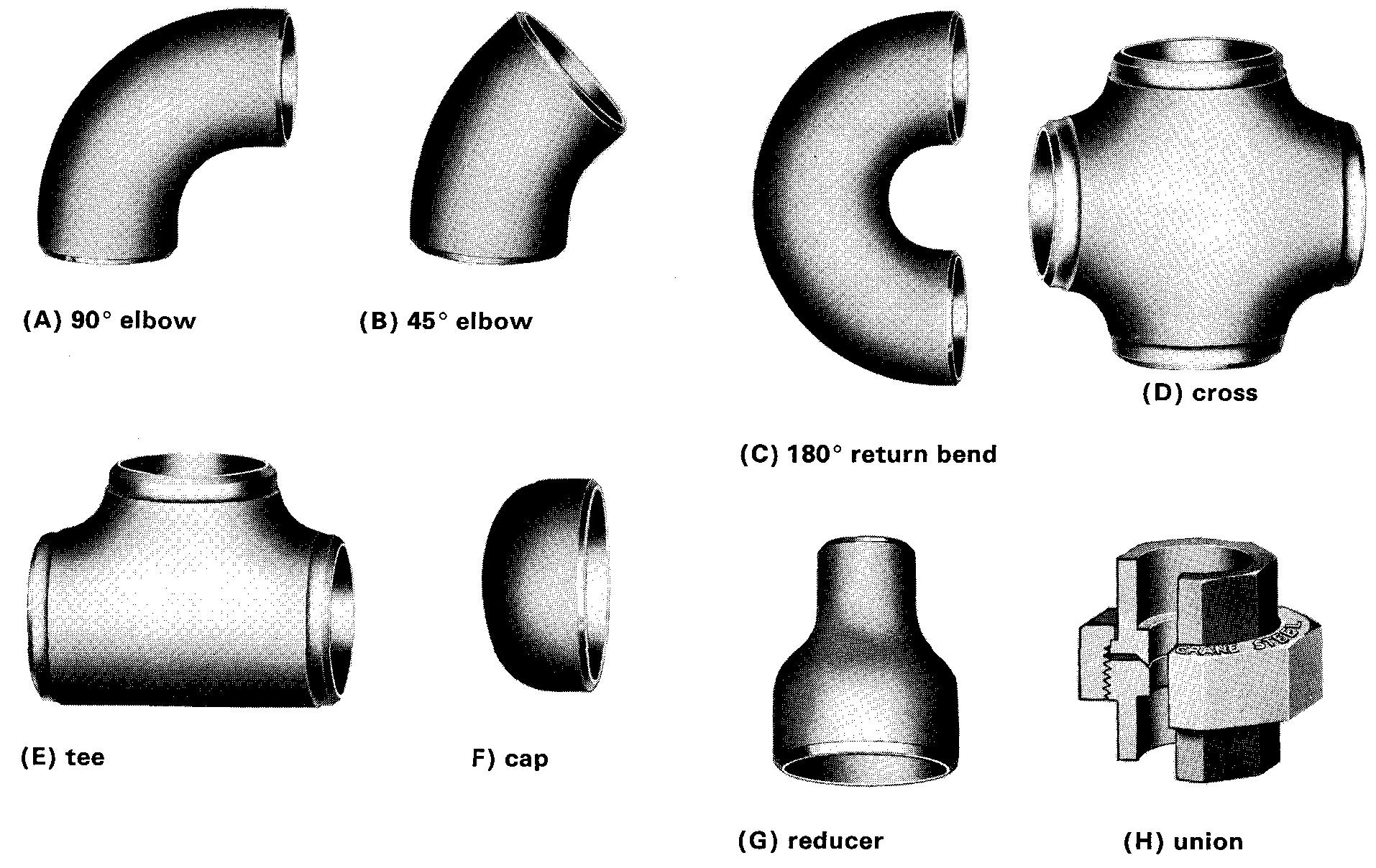
Welded joints are permanent, strong, and leakproof. Pipe line corporations use welded joints for connecting piping which often extends over hundreds of miles. Piping used in constructing guard and hand rails, fencing, and so on, is often welded.
Flanged fittings, shown in Fig. 20-7, are used for piping measuring larger than 2 inches.
fig. 20-7.Flanged fittings
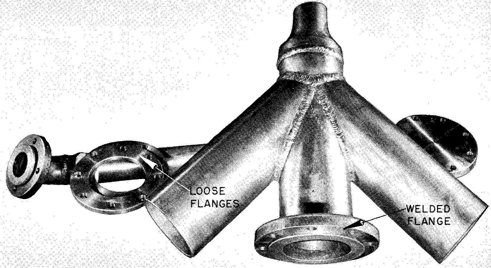
Flanged fittings are generally found on heavy industrial and commercial piping systems. Cast iron or steel piping is usually used for systems such as these.
Specifications of fittings
When parts lists are made up and drawings of piping systems are prepared, all pipe and all fittings should be accurately specified. The draftsman should be familiar with as many as possible of the kinds of pipe and fittings in common use.
The method of preparing a parts list varies from company to company. Some companies simply list the manufacturer's name and catalog number of the required fitting. Other companies require a more complete description of each of the fittings.
Complete specifications are available in manufacturers' catalogs and in ASA manuals. In most cases, the information necessary to describe a particular part can be found by checking these sources. In general, a fitting may be specified by simply giving the nominal size of the pipe to which it will be connected, the type of the fitting, and the material.
Valves
In a piping system, valves are used to permit the passage of, or to stop the flow of, liquids or gasses. Figure 20-8 shows two of the more common types of valves in use.
fig. 20-8. Valves
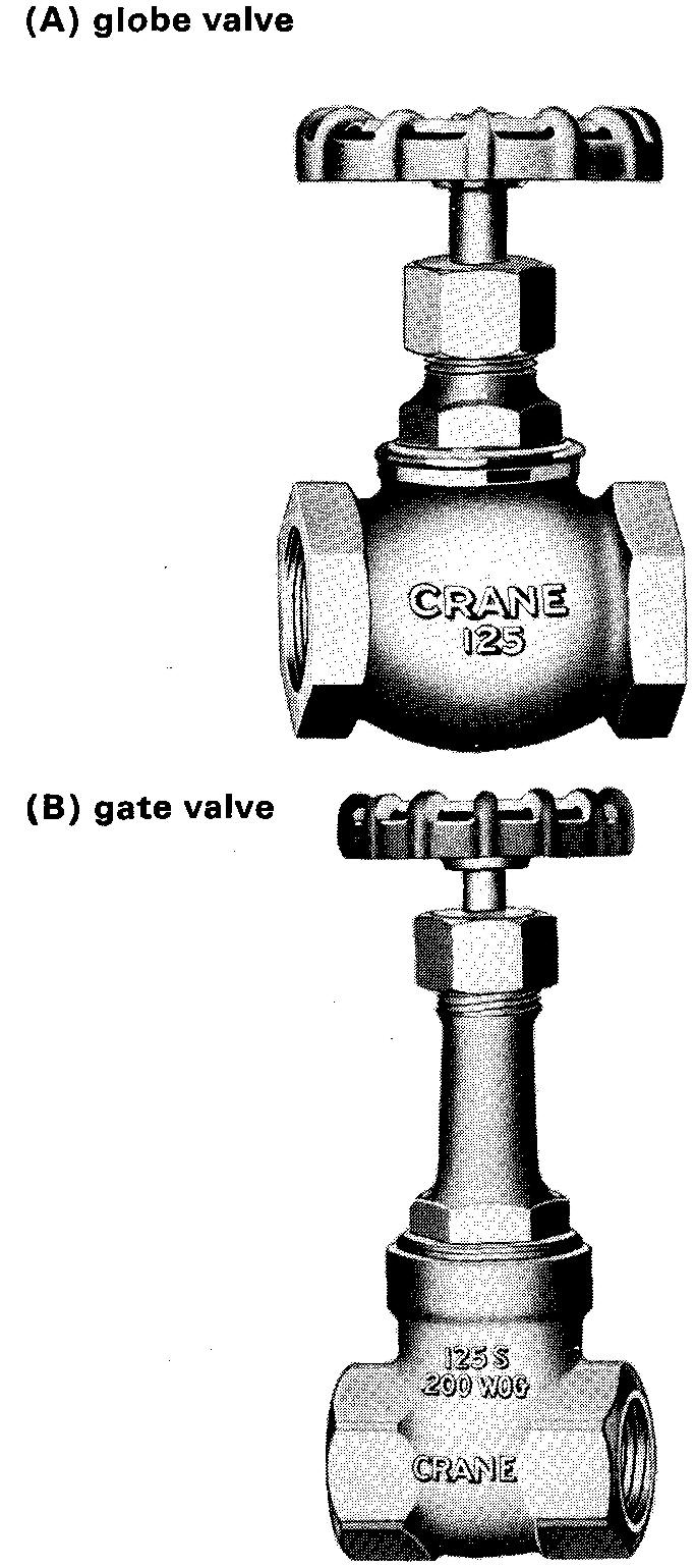
The globe valve is used for steam and fluids and in other cases where the volume of flow is not critical.
The gate valve is used for water and other liquids. Valves are often represented on a drawing in an open, or extended, position to ensure sufficient space to operate them. It is difficult to plan the required space if valves are drawn in a closed position.
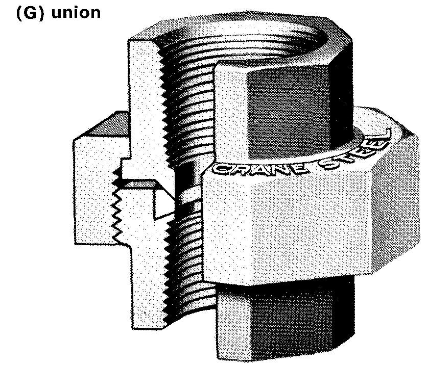
Unions
Piping systems which must be frequently or occasionally opened may be connected by unions. Figures 20-4G, 20-6H, and 20-9 illustrate types of unions.
The threaded type, Fig. 20-4G, is used on pipes measuring 2 inches or under. It can be disconnected by unscrewing the large collar.
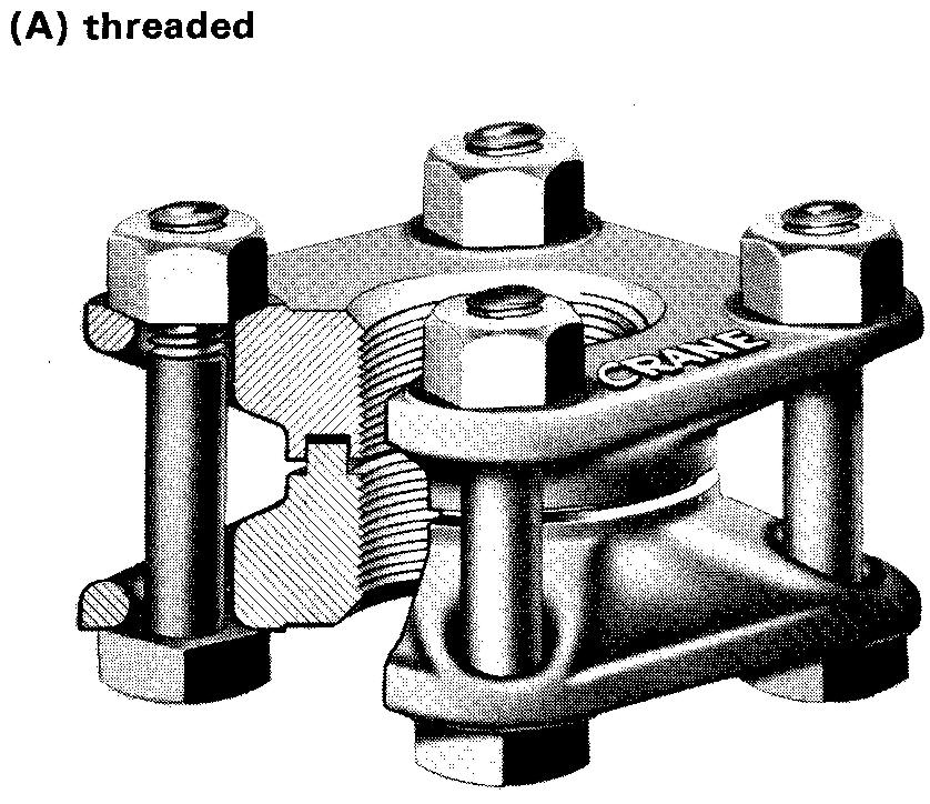
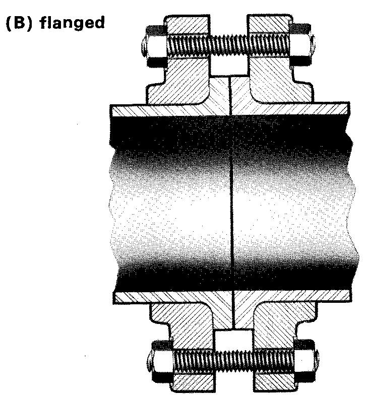
The collar may be similarly disconnected on the welded type union shown in Fig. 20-6H. The unions shown in Fig. 20-9 are used for larger pipe. They can be disconnected by removing the bolts which hold the two parts of the flange together.
fig. 20-9. Unions—screwed and flanged
Pipe threads
The American Standard pipe thread includes two general types: taper and straight, shown in Fig. 20-10.
fig. 20-10.Representation and specification of external pipe threads
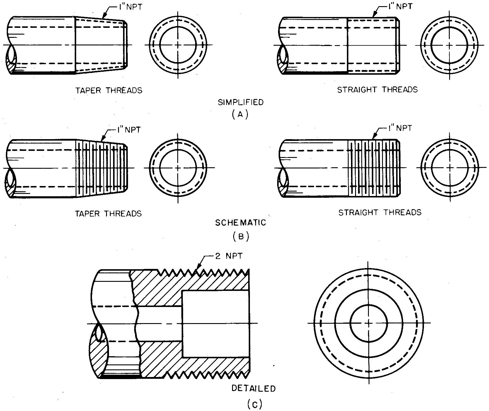
Taper threads are cut on a tapered surface. The taper measures 1/16 inch per foot. Straight threads are cut parallel to the axis, or center line, of the pipe. Both thread types can be made with the same number of threads per inch, the same thread form, and the same depth of thread.
Most of the time, taper threads are used for external threads (the thread on a water pipe, for example). External threads can also be straight threads. Straight threads are more commonly used for internal threads (the threaded hole on a pipe elbow or on a coupling, for examples).
Making up a pipe with a taper thread into a fitting having a straight thread results in a tight seal, since the mating threads adjust to each other.
Representing pipe threads
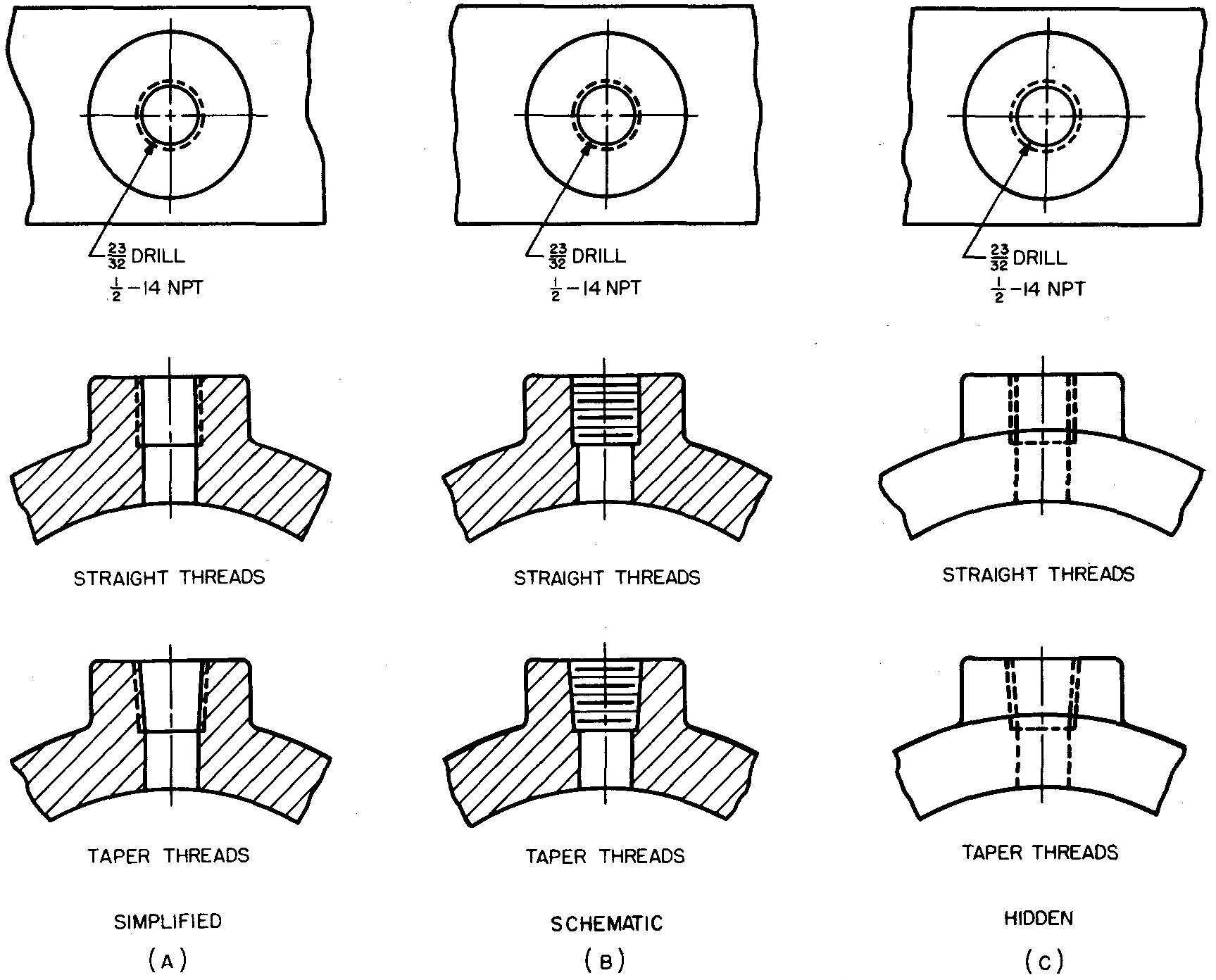
Pipe threads, like screw threads, may be represented on a drawing by using the simplified, schematic, or detailed form, regardless of the diameter of the pipe. The methods for illustrating pipe threads are shown in Figs. 20-10 and 20-11.
fig. 20-11. Representation and specification of internal pipe threads
On assembly drawings, sectional views of pipe threads are usually drawn in detailed thread representation, Fig. 20-10C.
For simplicity, taper pipe threads are often represented as straight threads. In any case, a note should specify the precise type of thread desired. In the drawing of taper threads, the taper is often exaggerated. See Figs. 20-10 and 20-11 for thread specifications.
Thread engagement
Thread engagement means the distance one part is threaded into its mating part so that a tight joint may be obtained. Thread engagement varies with the size of the pipe. Table 68 also lists the recommended distance for thread engagement for taper threads from 1/8 inch to 4 inches.
Sizes in the table may vary slightly from true size from thread to thread, but the sizes are considered accurate enough for most purposes. Information in the table is especially useful to the draftsman when he prepares a drawing of a piping system which may require an accurate layout.
The column headed Tap Drill Size aids the draftsman who must specify the correct tap drill size for threaded holes which fit mating parts.
Piping drawings
There are two kinds of piping drawings. Each kind may be used to show the location, specifications, and arrangement of the pipes and pipe fittings in a system. The two kinds will be separately illustrated and explained.
Ddouble-line drawings
Figure 20-12 shows an example of a double-line drawing made for the purpose of giving detailed information of the parts in a piping system. Double-line drawings are usually drawn to a large scale.
fig. 20-12. a Double-line piping drawing
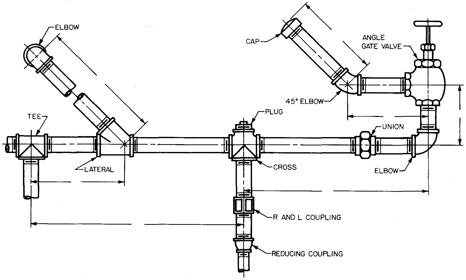
Scales less than 1/4 inch = 1 foot reduce the size of the fittings to the extent that the parts are often difficult to understand on the drawing.
Most draftsmen avoid using a scale of less than 1/4 inch = 1 foot for this reason. Long, continuous pipes are frequently drawn with a break so the entire system can be shown on one drawing.
The outside lines of the pipes are spaced to represent the outside diameter of the pipe. In general threaded fittings are represented by using the symbols as shown in Table 66 and Tables 68 through 70 and 72 through 75.
These symbols closely resemble the actual shape. Flanged fittings and welded fittings are usually drawn to scale. Sizes for any feature of a fitting omitted in the tables may be estimated and drawn to represent the approximate shape.
One, two, or three views of a double-line piping drawing may be drawn. One view is usually sufficient to show a complete installation when most or all of the pipe and fittings are to be installed in one plane, as shown in Fig. 20-12.
Two or three views may be required to supply the information for other more complicated piping systems. The main objection to the use of more than one view is that one or more pipes and fittings often extend behind or overlap with other pipes and fittings, thus making the drawing confusing and difficult to understand.
Specifications for parts are lettered in a note on the drawing and placed near the fitting. Leaders connecting the note to the fitting may be used if desired. A bill of material is usually drawn on the sheet.
Dimensions for pipes and fittings are always given from center-to-center. Pipe lengths are usually not given on the drawing. Established practice is to leave data such as this to the discretion of the pipe fitter.
Single-line drawings
Figure 20-13 is an example of a single-line drawing of a piping system, which is used to show the arrangement of pipes and fittings when drawn to a small scale.
fig. 20-13. A single-line piping drawing
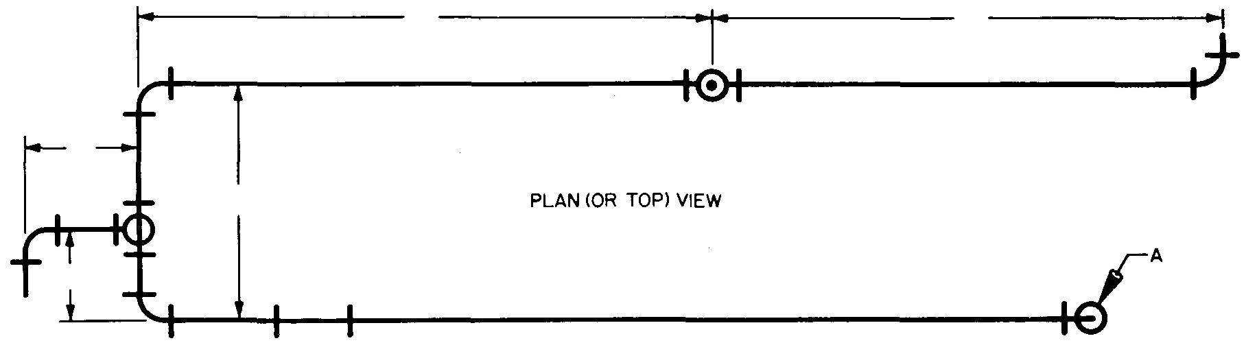
In this case, only the center lines of the pipes are drawn, regardless of the diameter of the pipes. The center line is represented as a solid line. Symbols for single-line drawings are given in Table 67. The drawing size of the symbols is left to the discretion of the draftsman.
They may be drawn with instruments or with the aid of commercial piping-symbol templates.
The scale of single-line drawings may be as small as 1/8 inch = 1 foot and the symbols may be drawn at a convenient size to represent the approximate shape. In some cases, a piping system may be represented in single line by one, two, or three views. Figure 20-13 shows a two-view layout.
Single-line drawings are comparatively easy to draw and thereby require less time than double-line drawings. They are often used on drawings which explain the principles of operating a piping system and on drawings for making studies or for repair work. Dimensions and specifications for pipe and fittings are placed on the drawing in the same way as they are on double-line drawings.
Special care must be taken in drawing turns or changes in direction of flow in the piping system when making a single-line drawing. For example, a 90° elbow with the flow away from the viewer would be drawn as in Fig. 20-13 at point A. The elbow turned so the flow is toward the viewer would be shown as in Fig. 20-13 at point B.
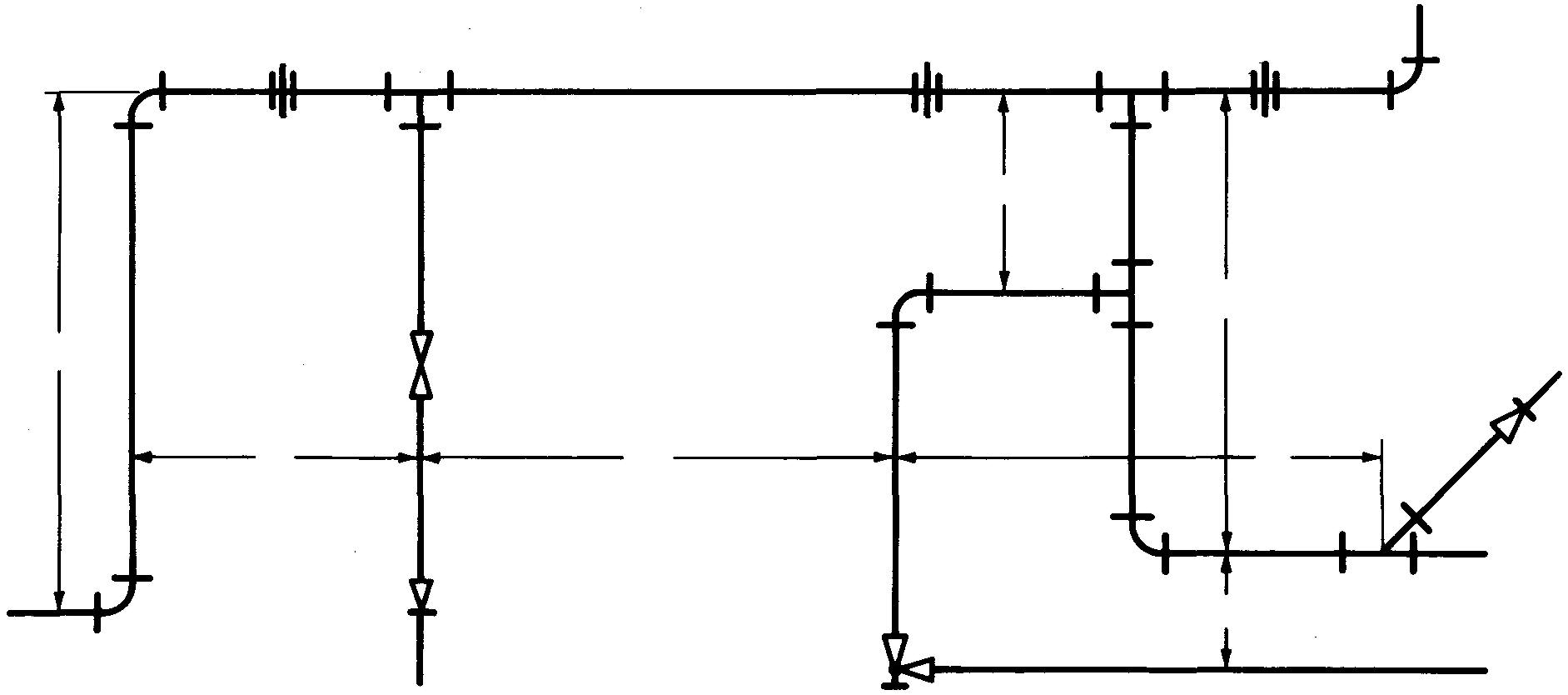
Developed views
Another method of making a single-line drawing, called a developed view, is to draw the pipes and fittings as if the entire system were swung or flattened into one plane, as in Fig. 20-14.
fig. 20-14. A developed view
Pictorial-diagram drawings
Figure 20-15, a pictorial-diagram drawing, shows the pipe and fittings as they would appear in space. This method is perhaps the clearest way of showing the location and arrangement of parts on a piping system. The change in direction and the different levels of pipes can be clearly shown.
fig. 20-15. A pictorial-diagram drawing
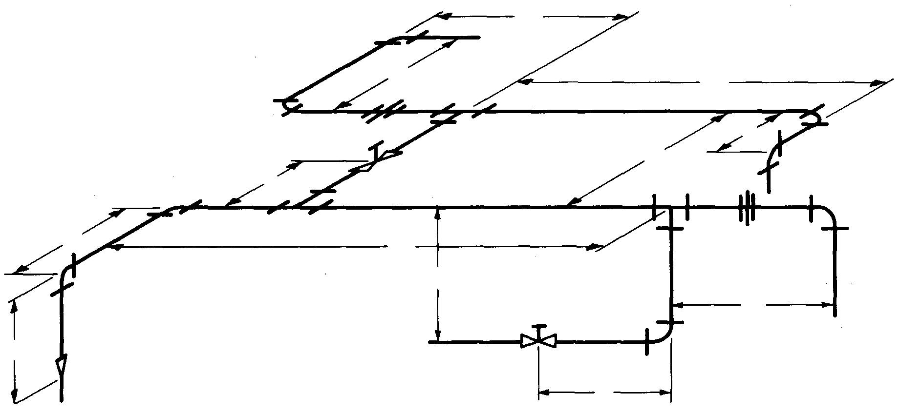
All vertical pipes are represented by vertical lines. Pipes which recede to the right or left are usually drawn at 30° or 45° angles. Symbols used for single-line drawings may also be used for pictorial-diagram drawings with only slight changes. The crossbars on the symbols are drawn so they appear to be lying in the plane formed by the bend of the pipe.
Preparing piping drawings
Most draftsmen make a freehand sketch before starting a piping layout. The scale of the drawing and the location of each of the various parts in the final position on the drawing may thus be planned. The appropriate symbols are selected from the tables. Considerable drafting time may be saved by preparing a rough sketch before making a final scale drawing.
The draftsman starts the drawing by laying out center lines for all of the pipe. Shorter center lines which mark the exact location of each symbol are then applied to the drawing. The pipe and symbols are next drawn. The drawing is completed by applying the necessary dimensions and notes and by adding the parts list.
Review questions (The answers are not given)
1. Why is cast iron piping not recommended for conditions requiring sudden strain?
2. Define corrosion.
3. What do the abbreviations ID and OD mean?
4. Which type of pipe would be recommended for carrying liquids under high pressure, cast iron or steel?
5. What is the difference between black pipe and galvanized pipe!
6. Which piping material is best for resisting corrosion: wrought iron or steel?
7. Which piping material is the most expensive: brass, steel, or iron?
8. Name one outstanding advantage of copper tubing when used for plumbing or heating in building construction.
9. Which kind of tubing can be bought in coils: hard or soft copper?
10. Under what conditions would lead and lead lined pipe be used?
11. Why is plastic pipe being increasingly used in piping systems?
12. Define nominal diameter and actual diameter of piping.
13. In what way do the three weights of steel and wrought iron pipe differ?
14. By what two methods is pipe which is used in a piping system specified on a drawing?
15. What is meant by pipe fittings!
16. Name the various methods of fastening pipe to fittings.
17. What is the purpose of pipe compound!
18. Under what conditions are welded fittings used?
19. What is the purpose of a valve!
20. What is the purpose of a union!
21. How may a fitting be specified on drawings?
22. How much does the taper measure on a tapered pipe thread?
23. In most applications, tapered threads are commonly used for which type of threads: external or internal? Straight threads?
24. Define thread engagement.
25. It is standard practice to represent taper pipe threads as straight threads on a drawing. Explain.
26. When a tapered thread is drawn, the taper is often exaggerated. Why?
27. What is the main purpose of a double-line piping drawing?
28. How are pipe fittings represented on double-line drawings?
29. Under what conditions may only one view of a double-line piping drawing be made?
30. Pipe lengths are usually not given on the drawing. These data are left to whose discretion?
31. What is the most important advantage of a single-line piping drawing?
32. What does the single line on a single-line drawing represent?
33. Describe a developed view.
34. Why are single-line drawings considered to be particularly useful?
35. A pictorial-diagram drawing is considered to be the clearest way of showing the parts in a piping system. Explain.
36. The symbols used for pictorial-diagram drawings are, with only slight changes, those used for what type of drawings?
37. What are some of the advantages in preparing a freehand sketch before making a piping drawing?
Problems
problem 20-1
Make a one-view double-line drawing of the piping system shown in Fig. 20-I.
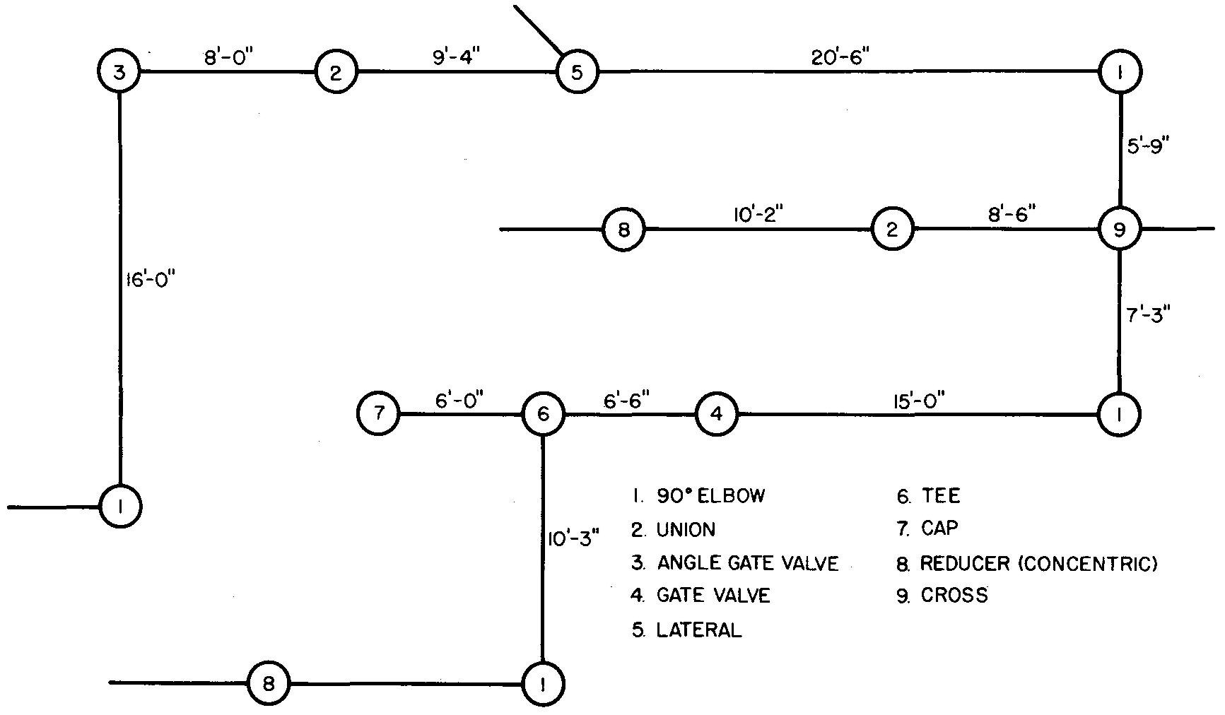
Use 1/2 inch and 1 inch wrought-steel pipe and 125 pound cast iron screwed fittings.
Dimension the location and identify each fitting with a note.
SCALE: 1/4" = 1' - 0"
problem 20-2
Make a one-view single-line drawing of the piping system shown in Fig. 20-I.
Use hard copper pipe and soldered fittings. Omit dimensions and notes.
SCALE: 1/4" = 1' - 0"
problem 20-3
Make a one-view single-line drawing of the piping system shown in Fig. 20-I.
Use brass pipe and screwed fittings. Omit dimensions and notes.
SCALE: 1/4" = 1' - 0"
problem 20-4
Make a one-view double-line drawing of the piping system shown in Fig. 20-II.
Fig. 20-II
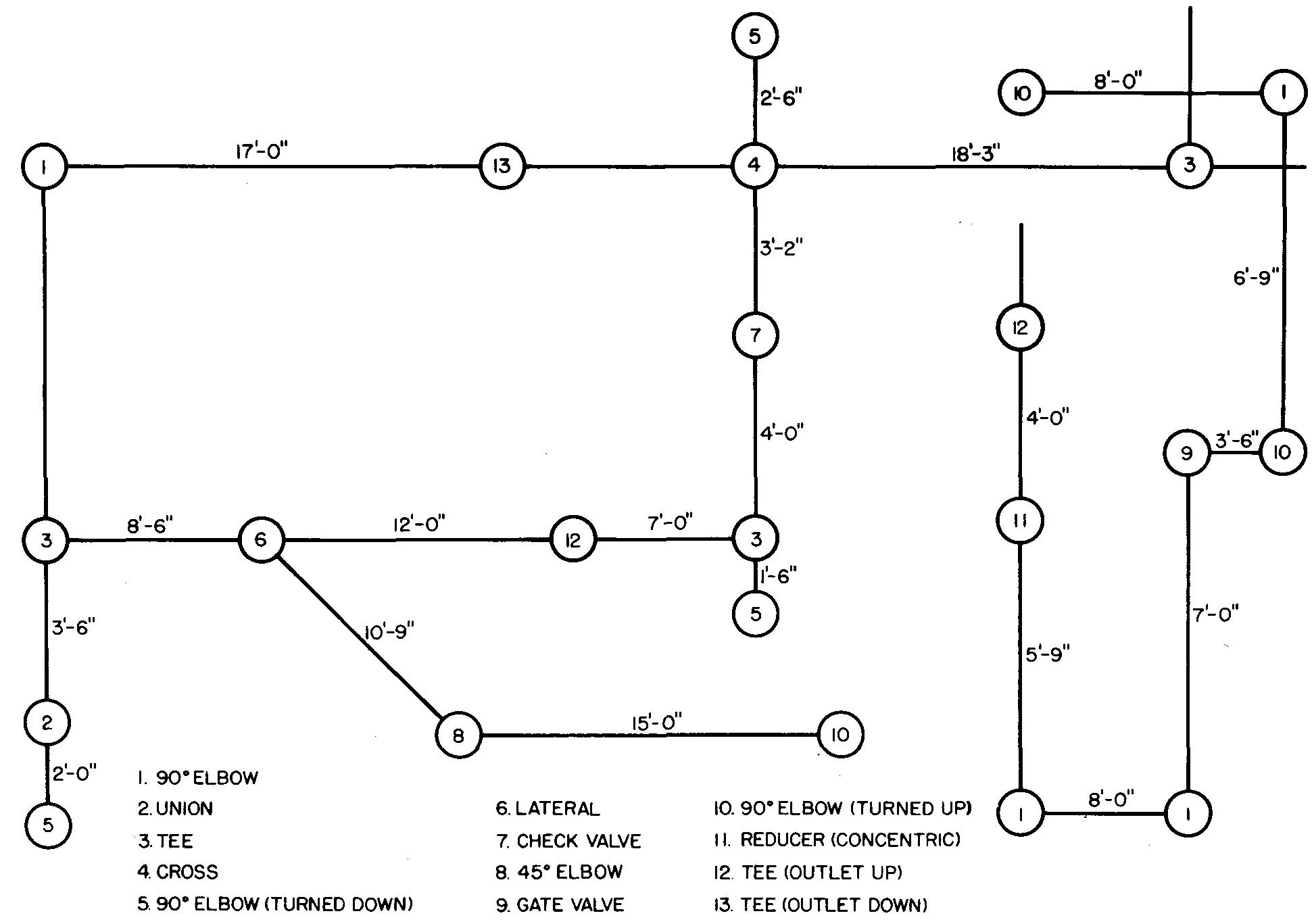
Use 3/8 inch and 1/2 inch brass pipe and screwed fittings.
problem 20-5
Make a developed view of the piping system with screwed fittings as shown in Fig. 20-II.
The plan (top) view is shown.
Dimension the location of each fitting. Omit notes.
SCALE: 1/4" = 1' - 0"
problem 20-6
Make a pictorial-diagram drawing of the cooling system shown in Fig. 20-II.
Draw the layout approximately four times the size of the illustration in the book.
Represent all parts other than the pipe and fittings approximately as shown on the pictorial drawing, Fig. 20-III.
figure 20-III
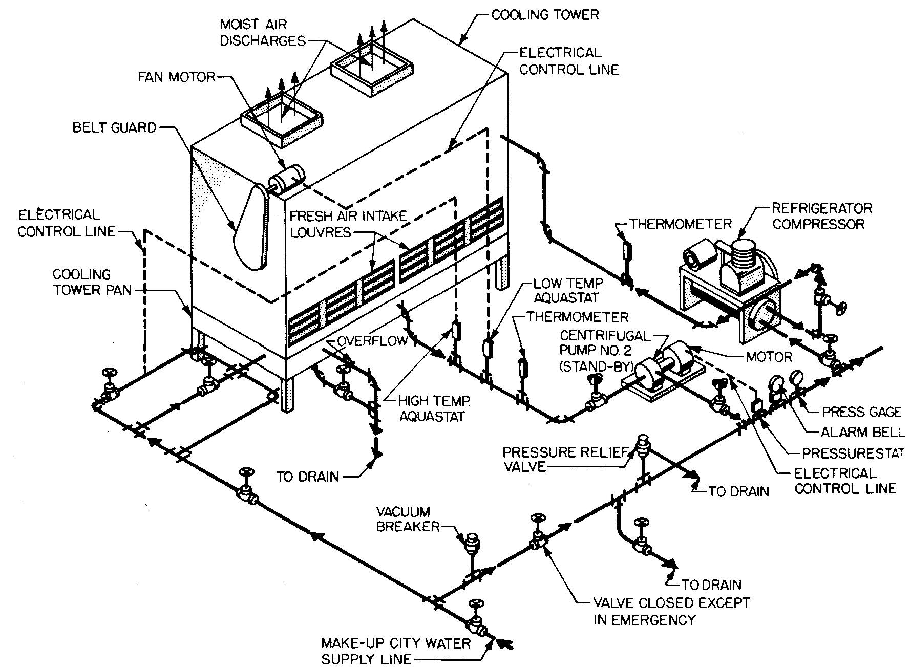
Apply all given notes to your drawing and label all parts.
Omit dimensions.
All valves shown are gate valves.
Use 1/2 inch brass pipe and screwed fittings.
problem 20-7
Make a pictorial-diagram drawing of the piping system and quenching system shown in Fig. 20-IV.
figure 20-IV
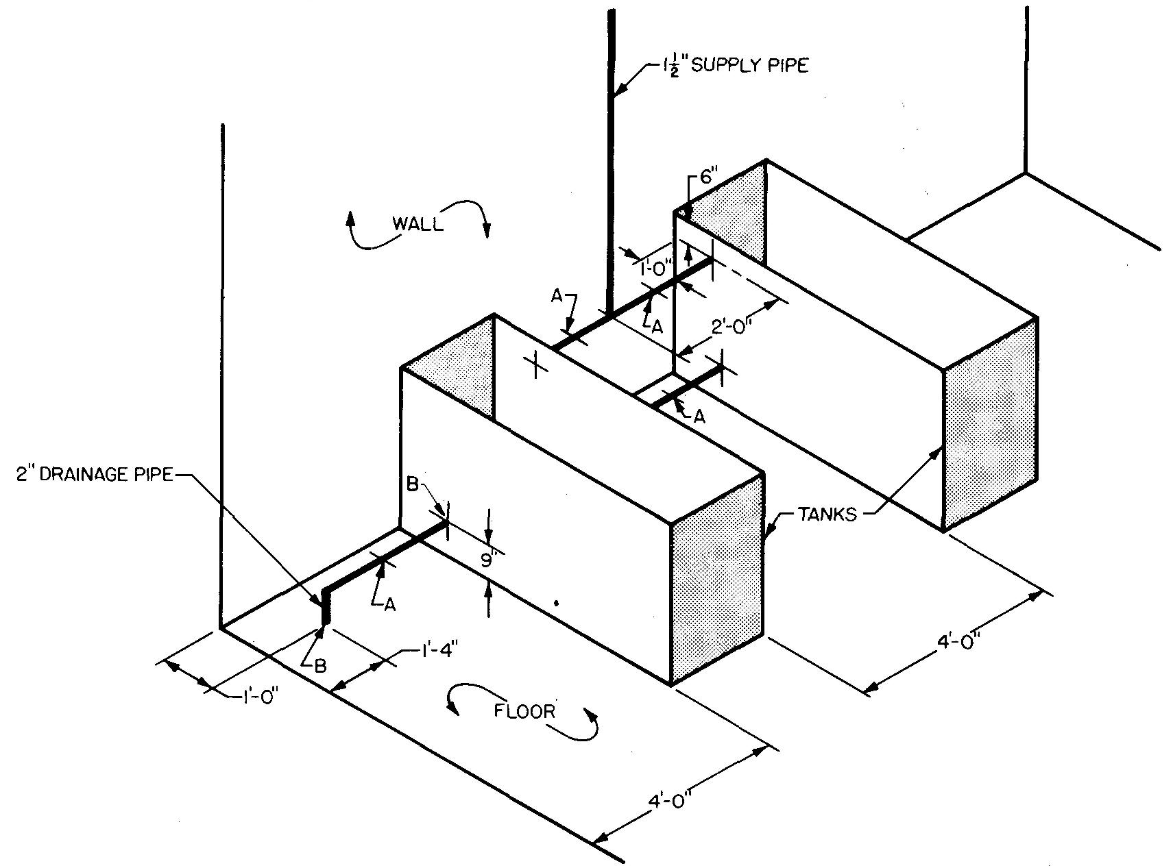
The tanks are 2 feet wide by 3 feet deep and 6 feet long.
Calculate to the nearest gallon the capacity of water each tank will contain and also the total weight of each tank filled to the supply level.
Each tank weighs 120 pounds.
(Water weighs 62.5 pounds per cubic foot; 1 gallon of water equals approximately 1/8 cu. ft.)
Connect existing supply and drainage pipes to tanks.
Install gate valves at locations marked A on illustration.
Use 2 inch wrought-steel pipe and 250 pound cast iron screwed fittings.
Use a welded flange at typical floor and tank positions marked B.
Locate and identify each fitting.
SCALE: 1/2" = 1' - 0"
problem 20-8
Make a two-view single-line drawing of the piping system (including the tanks) as shown in Fig. 20-IV.
Dimension the location of each fitting and the tank sizes.
Prepare a bill of material for all pipes and fittings. (See Problem 20-7 for sizes and specifications.)
SCALE: 1/2" = 1'-0"
problem 20-9
Make a pictorial-diagram drawing of the piping system shown in Fig. 20-V.
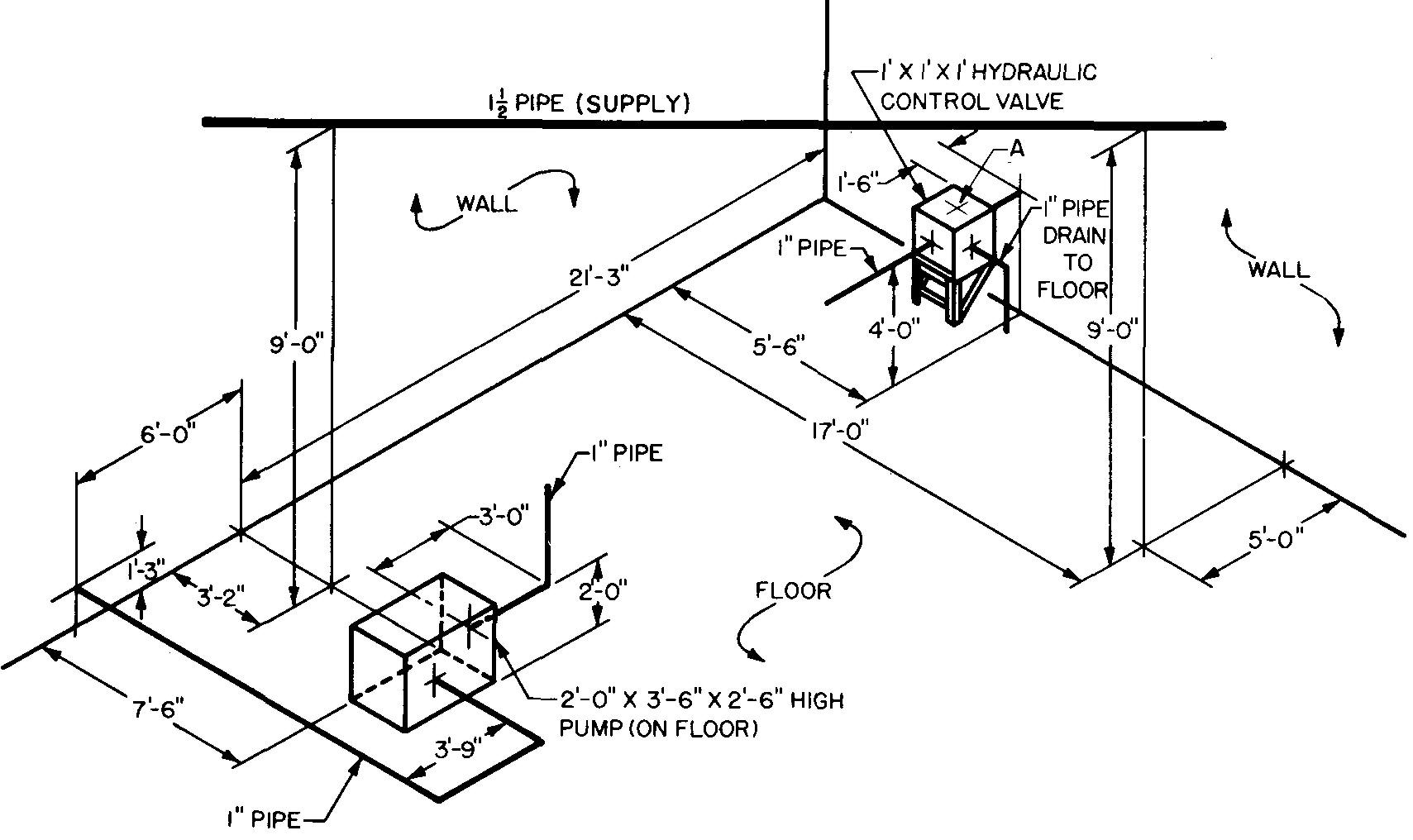
Design a piping system as follows:
1 .Connect the hydraulic control valve to the pump.
2. Connect the supply pipe to the hydraulic control valve at the position marked A.
3. Show the proper fittings at each joint. Locate by dimension and identify each fitting. Use wrought-steel pipe and 125 pound cast iron fittings.
SCALE: 1/4" = 1' - 0"
![]()