Principles gear drawings
See Also : Engrenage
Introduction
Gears are machine elements which are used to transmit motion and power.
Except for the spur gear and rack, the power is transmitted by successively engaging the teeth from a gear mounted on a rotating shaft with the teeth of a second gear mounted on another rotating shaft. The spur gear and rack, Fig. 19-2D, are used to change rotary motion to linear (or straight line) motion.
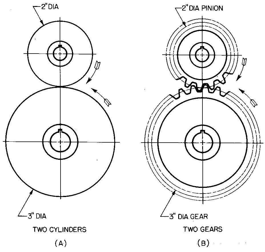
The principle of gears may be better understood by comparing the two cylinders or wheels shown in Fig. 19-1 A. In this case, the cylinders which are mounted on parallel shafts are rolling or rotating in contact with one another.
fig. 19-1. Friction wheels and spur gears
The smaller cylinder, being two-thirds as large in diameter as the other, would make three revolutions (or turns) to every two revolutions of the larger cylinder. The speed of the 2-inch diameter cylinder would then be one and one-half times as fast as the speed of the 3-inch diameter cylinder.
Thus, the speed ratio of the small cylinder compared to the large cylinder would be 3 to 2. The speed ratio of the large cylinder compared to the small cylinder would be the opposite, or 2 to 3.
NOTE: These ratios may also be written as 3:2 or 3/2 and 2:3 or 2/3.
Cylinders with smooth edges, such as those shown in Fig. 19-1 A, would slip. To prevent slipping, teeth are cut on the edges, as shown in Fig. 19-1B. The teeth of one gear mesh or interlock with the spaces between the teeth of the other gear. We may think of gears as cylinders with teeth cut on the edges.
Of two gears that run together, the one with fig. 19-1. friction wheels and spur gears
the smaller number of teeth is always called the pinion. The one with the larger number of teeth is called the gear. When a pinion drives a gear, the speed is reduced.
The reverse is also true; a gear driving a pinion increases the speed. Engineers have made wide use of this principle.
Gears are commonly used in industrial and business machines, gasoline and diesel engine drives, and in countless other applications.
Gear materials
Gears are made from cast iron and cast steel, carbon steel, alloy steel, powder metals, forged metals, bronze, aluminum, and brass. Many kinds of nonmetals are used, such as impregnated fabrics and fibers, nylon, and rawhide.
The selection of the kind of gear materials depends upon the conditions of their use, such as strength or wear requirement, quiet-running, or corrosion-resisting requirements.
In general, the pinion is often made of a harder material than the gear to compensate for increased wear. Gear drawings should include the required material specifications and necessary heat treatment and hardness range.
Basic forms of gears
There are a number of different kinds of gears. The basic forms shown in Fig. 19-2 are the most common. The study of gears in this text will be limited to spur gears, bevel gears, and the worm gear and worm.
Designing gears
Commercially available gears are specified on drawings and are used whenever possible. However, machine draftsmen should have a thorough understanding of gears for such times as the draftsmen are required to draw and dimension them.
Gear design includes the selection of the gear sizes, pitch diameter, center distance, size and form of the teeth, shaft diameter, speed ratios, and appropriate materials. Most of these factors are usually worked out by the design engineer.
In actual practice, the designer may provide the draftsman with a few basic dimensions of the gear he wishes to use.
For a spur gear, for example, the designer may give the draftsman the pressure angle, diametral pitch, and number of teeth. These terms are discussed in Sec. below.
Generally, all other dimensions which are needed in order for the gear to be drawn and manufactured are worked out by the draftsman. A thorough study of the following topics applying to spur, bevel, and worm gearing is important.
Spur gears
Gears of this type, used to transmit rotary (or circular) motion from a gear on one shaft to a gear on a parallel shaft, are called spur gears. They are generally used on drives requiring moderate speeds, such as those for marine equipment, hoisting equipment, meta. cutting machines, and mill drives.
Spur gear terms and formulas
See Also : Spur Engrenage formule / Spur Gear Formulas
Before a drawing of a gear is made, the draftsman must work out a number of values, using mathematical formulas.
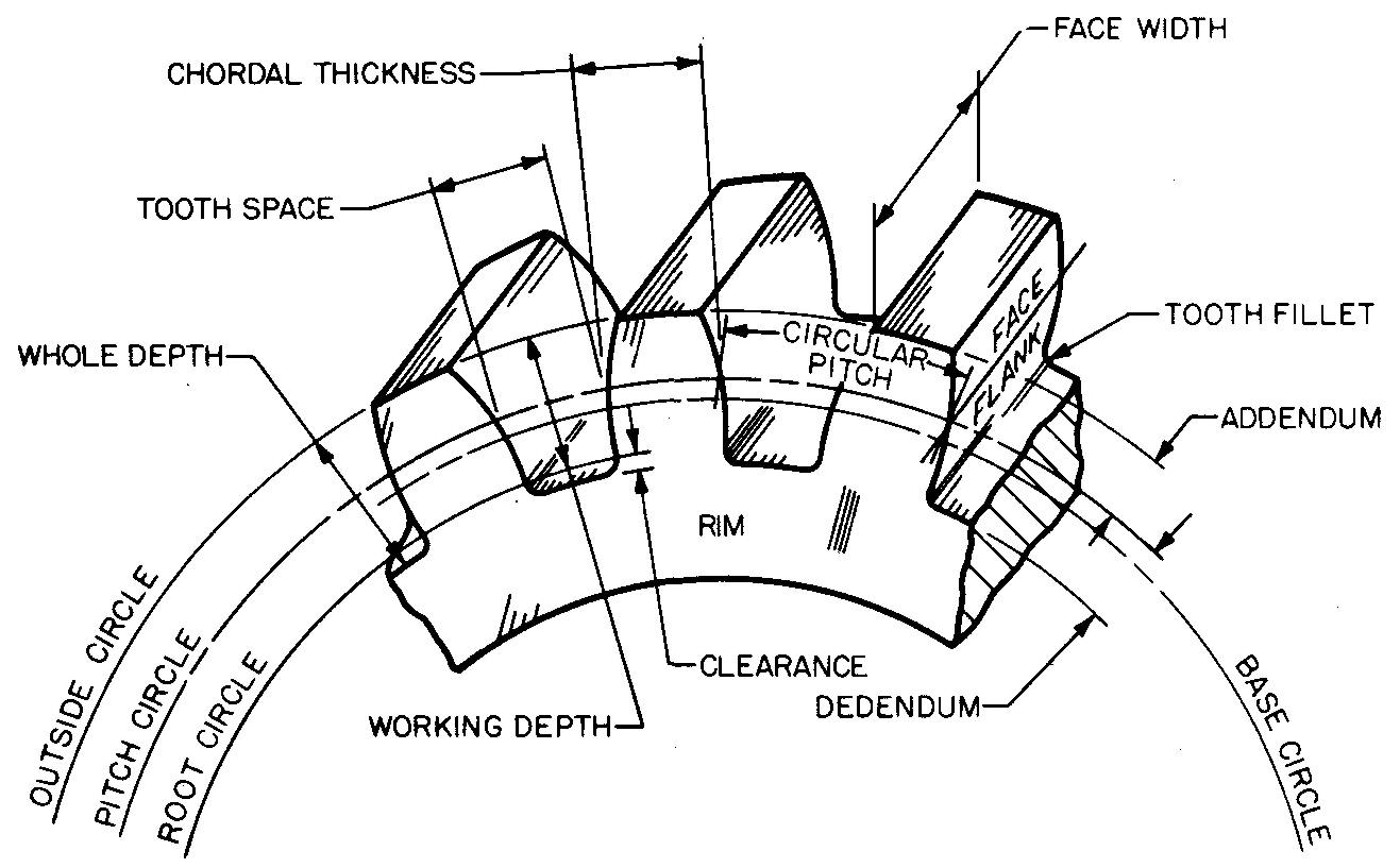
Spur gear terms and formulas are given in Fig. 19-3. Most of the terms have been adapted for use in this text by using simplified letter symbols. Other simplified symbols used to describe terms for bevel and for worm gearing are presented later in this chapter. Similar information, but presented in a more technical form, may also be found in standard commercial gearing catalogs or in engineering handbooks.
fig. 19-3. Spur gear terms and formulas
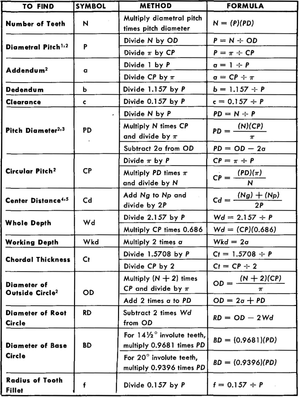
1 A ratio equal to the number
of teeth on a gear per inch of diameter of pitch circle.
2 Use
π =
3.1416.
3 The diameter of the circle labeled Pitch Circle in Fig. 19-3.
4
Distance measured from the center of a gear to the center of its mating pinion.
5 Ng = Number of teeth for the gear Np = Number of teeth for the pinion.
Detail drawings for spur gears
Individual gear teeth are not shown on the drawing when they are to be cut from a gear blank. A gear blank is a cylindrical piece of metal sized to the general gear outline but without teeth, resembling the friction wheels shown in Fig. 19-1A.
The required tooth shape may be produced by either of the methods shown in Figs. 19-4 and 19-5.
fig. 19-4. Hobbing teeth on a spur gear
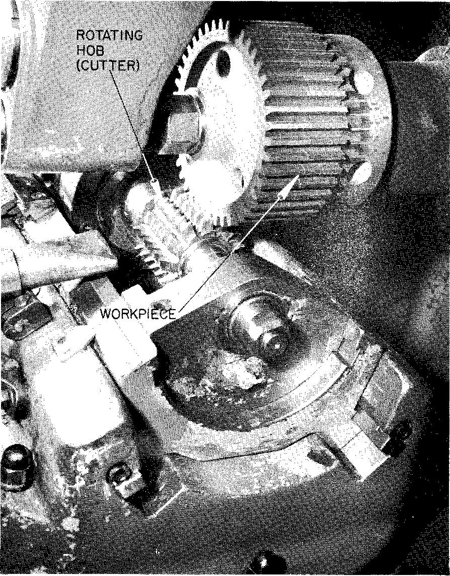
fig. 19-5. Broaching spur gear teeth
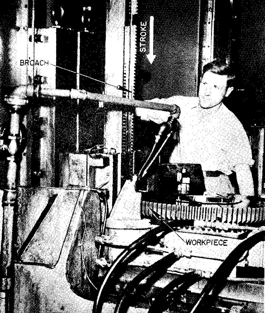
A drawing showing the tooth curves would not provide any needed information to the shopman since standard cutters are used to produce the desired tooth shape. Fig. 19-6 shows a typical detail drawing of a spur gear.
fig. 19-6. Detail views of a spur gear
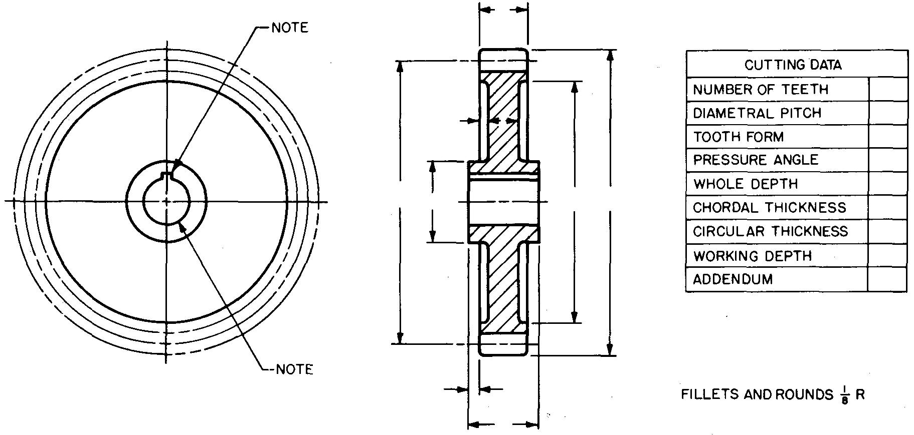
Two views are shown, but often a single view is sufficient. Dimensions for making the gear blank are given on the views. Dimensions for cutting or machining the teeth are given separately in the table entitled cutting data.
Some spur gears are roughly formed to shape by casting. The teeth are cast oversize and are later cut to final size by special cutters in the shop. Some companies prefer to show a few of the teeth on the drawing as an aid to the patternmaker who makes a wood model or pattern of the gear before it is cast. (Such a drawing is shown in Fig. 19-7.)
fig. 19-7. Detail views of a spur gear
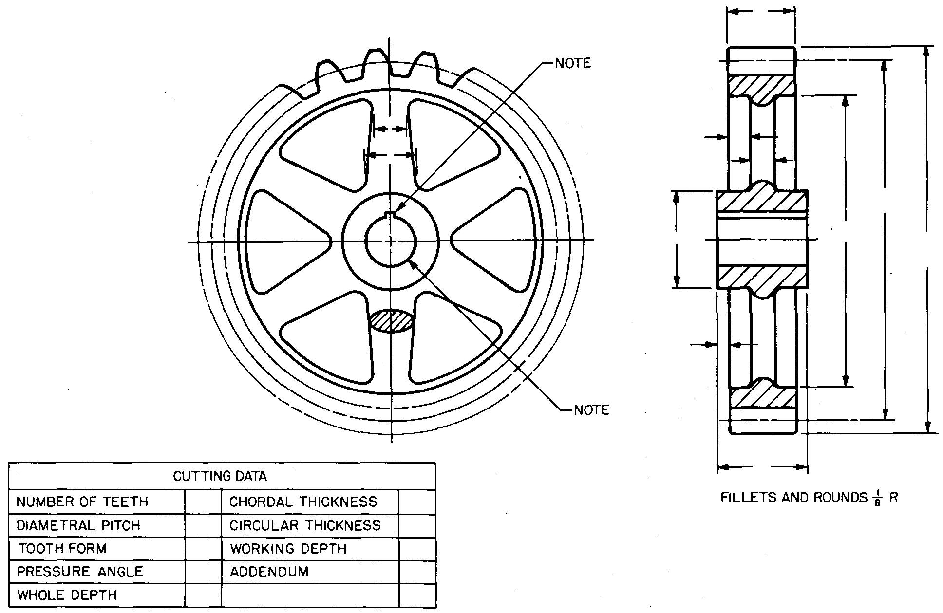
Only a conventional or approximate representation of two or three teeth is drawn. (In some special cases all of the teeth are shown.)
There is a considerable saving of drafting time when the teeth are not drawn to an accurate scale. Figure 19-8 shows still another method of preparing detail drawings of spur gears. In this case, both the gear and the pinion are shown with the gear and pinion blank dimensions and the cutting data.
Assembly drawings for spur gears
For assembly or display drawings, the draftsman should draw both the gear and the pinion engaged, or in mesh.
Depending upon the drafting practices of the particular company, the draftsman may omit the teeth entirely, as in Fig. 19-8; he may show only a few teeth, as in Fig. 19-9; or he may be required to draw all of the teeth.
fig. 19-8. Detail views of a spur gear and pinion
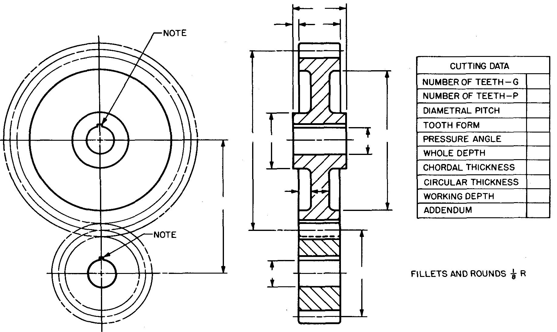
fig. 19-9. Assembly views of a spur gear and pinion
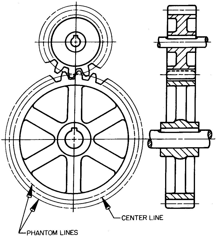
The methods shown in Figs. 19-6 and 19-7 are the most common, since drawing all of the teeth is tedious and time consuming. The teeth are represented by drawing the outside circle, the pitch circle, and the root circle. Note the types of lines used for each circle in the circular views, Fig. 19-9.
Other spur gear features
Views of gears are frequently shown in full section. It must be remembered that section lining is applied only to cut areas of the hub and rim and is omitted on spokes, holes, and key ways. Revolved sections are drawn to show the size and shape of the gear spokes.
Sectioning principles, as outlined in section 4 Principles of sectional views, should be carefully followed.
Over the years, gear designers have developed a series of rules and formulas based upon certain proportions of gear elements. These are called empirical formulas or rules of thumb. While the proportions are only approximate, they are considered accurate enough for most purposes.
Figure 19-10 shows examples of solid, webbed, and spoked spur gears. Also shown are some of the suggested proportions of the features.
fig. 19-10. Suggested proportions for spur gear features
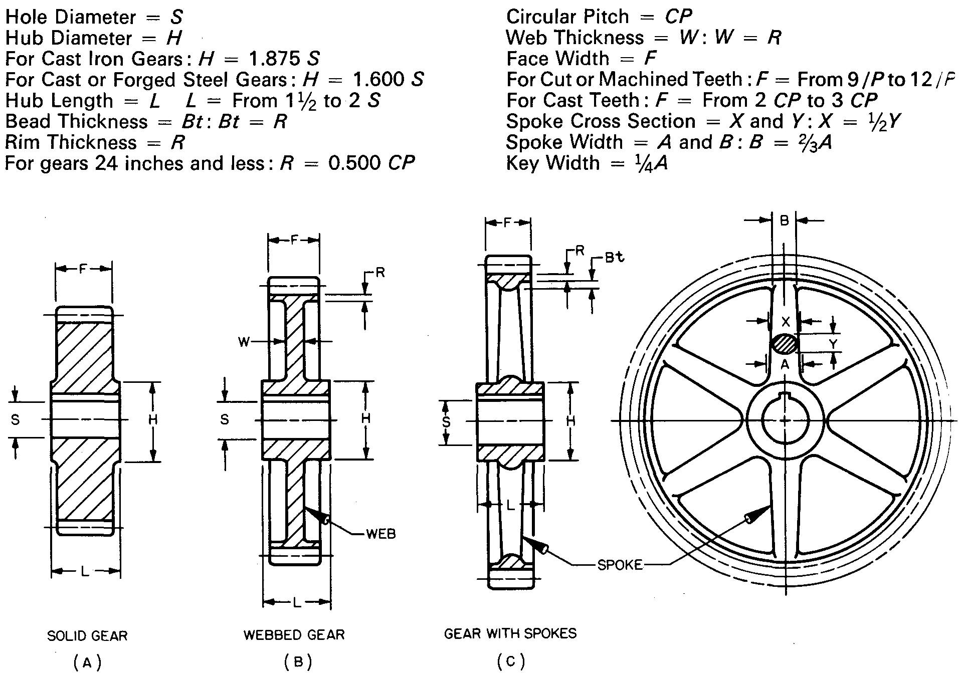
Occasionally it may be necessary to change some of the values slightly to suit existing conditions.
If the hub diameter, or some other feature, works out to be an odd size, such as 1.5062 inches, for example, the figure may be adjusted or rounded off to a simple figure as 1-1/2 inches.
Small pinions or small gears are usually made solid without spokes as in Fig. 19-10A.
The weight of larger gears may be reduced by connecting the rim to the hub with a solid web, Fig. 19-10B.
The weight may be further reduced by using spokes. Most gears are designed with four, five, or six spokes spaced equally, as in Fig. 19-10C.
Gear finishing
The surfaces on the top and sides of the teeth on most gears are finished by cutting, grinding, shaving, or lapping. The method of finish may be specified in a note on the drawing.
Finish symbols are usually omitted on the top and side surfaces and for all tooth surfaces. However, depending upon individual company standards, finish symbols may be applied to the sides of the rim and on the ends of the hub.
The full depth involute tooth
The most common tooth forms are the 14-1/2° and the 20° full depth involute. These forms differ only in the pressure angle. For gears having involute teeth, the pressure angle is the angle between the pressure line and a line tangent to the pitch circle, as shown in Fig. 19-11 A.
fig. 19-11. Layout of spur gear teeth
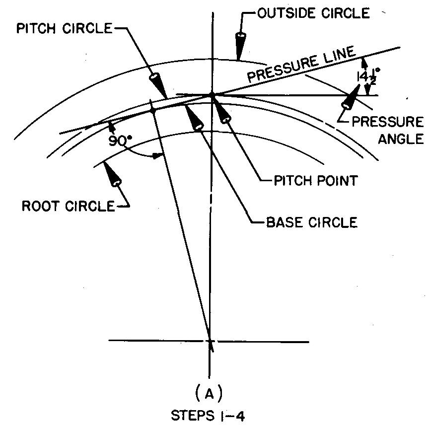
The pressure angle regulates the direction of pressure between the engaging teeth. The 20° pressure angle makes the tooth wider at the base; therefore a tooth with a 20° pressure angle is stronger than a tooth with a 14-1/2° pressure angle.
Drawing spur gear teeth
There are two methods for drawing teeth with the involute full depth form. One method is to use specially prepared tables, Grant's Involute Odontograph Tables, for finding the radii of the tooth curves. This method is explained in Example 1.
See also A Handbook on the Teeth o f Gears page 8 and 21
Another method is to construct the tooth curve with one radius. This Single Curve Method, used only when there are 37 or more gear teeth, is explained in Example 2.
Both methods produce only approximate tooth curves, rather than the actual curves, but either method is considered satisfactory for practically all gear drawing requirements.
Example 1
Draw a spur gear tooth, using Grant's Involute Odontograph Tables.
specifications
Pressure angle = 14-1/2°, diametral pitch = 2, and number of teeth =12.
procedure
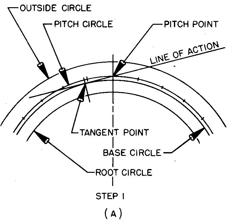
Draw the base circle as shown in Fig. 19-11A and as described in steps 1 through 4.
1. Refer to Fig. 19-3 and work out the values for the chordal thickness, the fillet radius, and the diameters for the outside, pitch, and root circles.
2. Draw the main center lines of the gear and swing arcs for the outside, pitch, and root circles.
3. Through the pitch point (the point where the main center line crosses the pitch circle) draw the pressure line, so that it makes an angle of 14-1/2° with a line tangent to the pitch circle at the pitch point.
4. Draw a line from the center of the gear, making an angle of 90° to the pressure line. Through this intersection point swing an arc of the base circle tangent to the pressure line. Thus the base circle may be found by laying out the pressure angle. (The draftsman uses the base circle when drawing the tooth curves.)
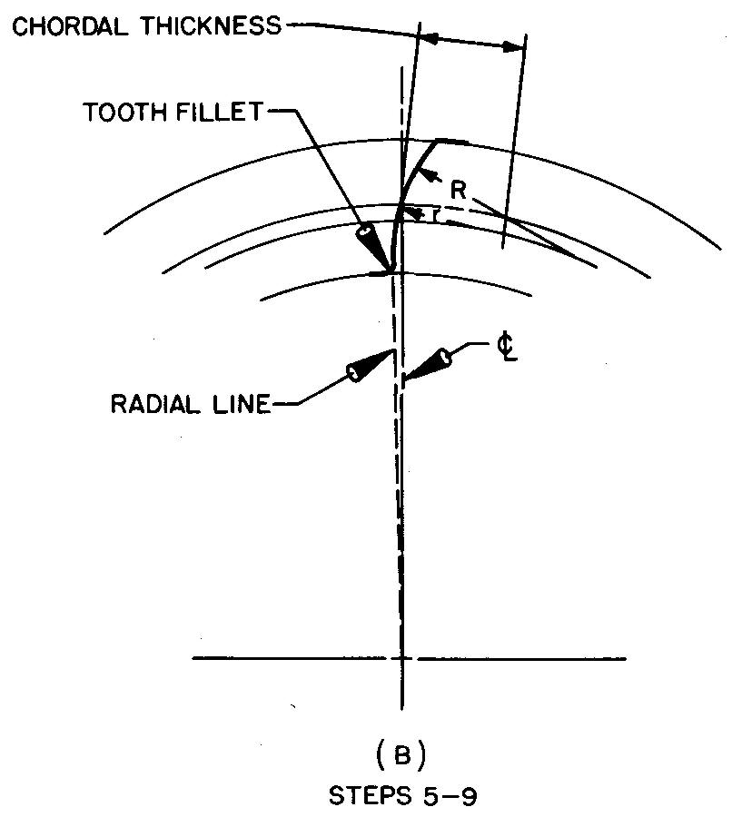
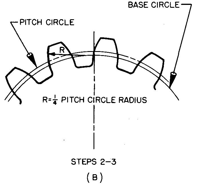
Draw one side of the tooth as shown in Fig. 19-11B and as described in steps 5 through 9.
5. Starting at the pitch point, lay off the chordal thickness on the pitch circle.
6. Refer to Grant's Involute Odontograph Table, Fig. 19-12, for the values of the face and flank radius.
fig. 19-12. Grant's odontograph table for 14'/2° involute gear teeth
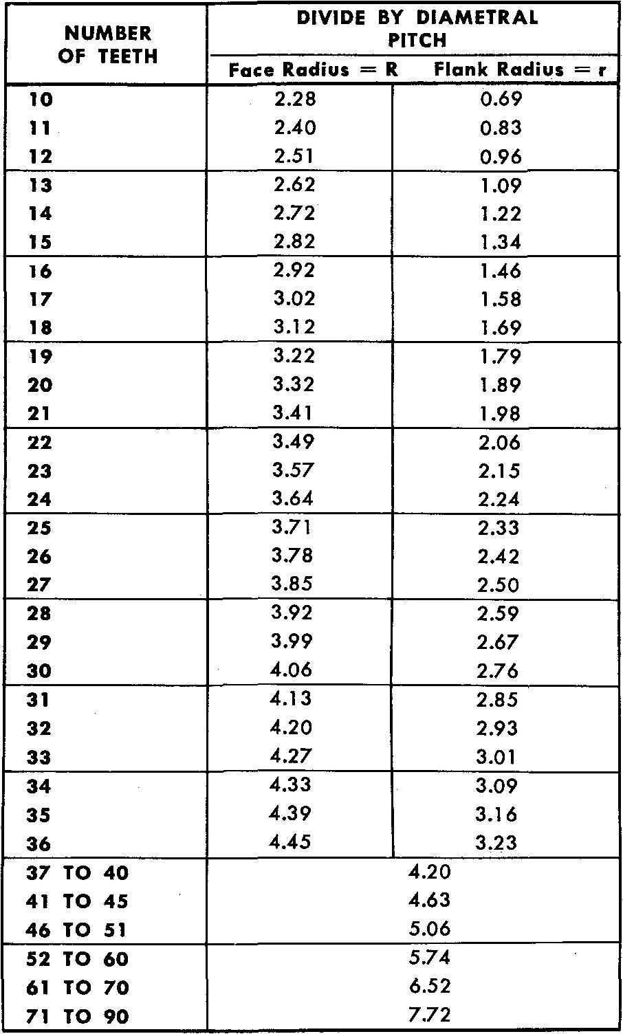
Reading across the line for a gear with 12 teeth, find the face radius (R), 2.51 inches.
The flank radius (r), also read across the line for a gear with 12 teeth, is 0.96 inch.
The column heading directs us to divide by diametral pitch.
In this example, diametral pitch = 2; therefore, R = 2.51 inches / 2, or 1.255 inches, and r = 0.96 inch / 2, or 0.48 inch.
7. Adjust the compass to the correct face radius (1.255 inches). Next, set the compass point on the base circle and swing an arc, forming the face of the tooth. The arc should cut through the pitch point and should extend from the outside circle to the pitch circle.
8. Adjust the compass to the correct flank radius (0.48 inch). Set the compass point on the base circle and swing a second arc, forming the flank of the tooth. The arc will be tangent to the arc of the face of the tooth, drawn in step 7. The arc should extend only to the base circle.
9. Draw a radial line
(extending from the center of the gear) and the tooth fillet, completing one
side of the tooth.
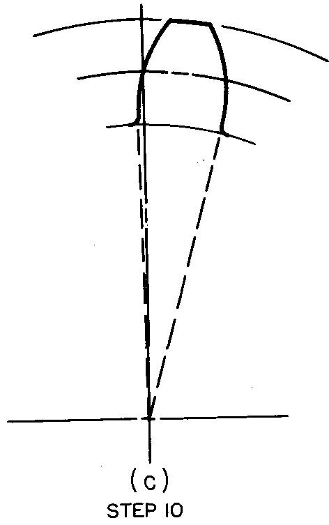
Complete the tooth as shown in Fig. 19-11C and as
described in step 10.
10. In the same manner, draw the arcs of the face and flank radius on the opposite side of the tooth. Draw the radial line and fillet, completing the entire tooth curve.
NOTE: In actual practice, the draftsman would save time by drawing the face and flank radii on both sides of the tooth with each respective compass setting.
example 2
Draw spur gear teeth, using the single curve method. For gears having 37 or more teeth, only one curve is drawn. The value for the radius of the curve may be obtained from Grant's Involute Odontograph Table, or it may be approximated as shown in the following example. The radius of the single curve is swung from the base circle.
Specifications
Pressure angle = 14-1/2°, diametral pitch = 2, and number of teeth = 40.
Procedure
Draw the base circle and the chordal thickness as shown in Fig. 19-13 A and as described in step 1.
fig. 19-13. layout of spur gear teeth
1. Refer to steps 1 through 5 of Example 1, as shown in Fig. 19-11.
Draw the teeth as shown in Fig. 19-13B and as described in steps 2 and 3.
2. With R equal to one fourth of the pitch circle radius, swing arcs with centers on the base circle, thus forming the curve on each side of the tooth.
3. Complete the tooth curve by drawing radial lines tangent to the arcs at the base circle and draw the tooth fillets.
Bevel gears
Like spur gears, bevel gears are used to transmit rotary motion from a gear mounted on one shaft to a gear mounted on another shaft, as shown in Fig. 19-2B.
Unlike spur gears, the shafts are not parallel, but are usually at right angles to each other. Bevel gears are used to change the direction of rotation and to increase or decrease speeds.
When both gears have the same number of teeth, have equal diameters, and are at right angles to each other, as shown in Fig. 19-14, they are called miter gears.
fig. 19-14. Miter gears
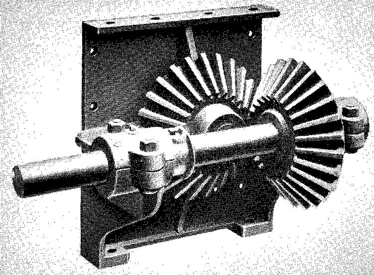
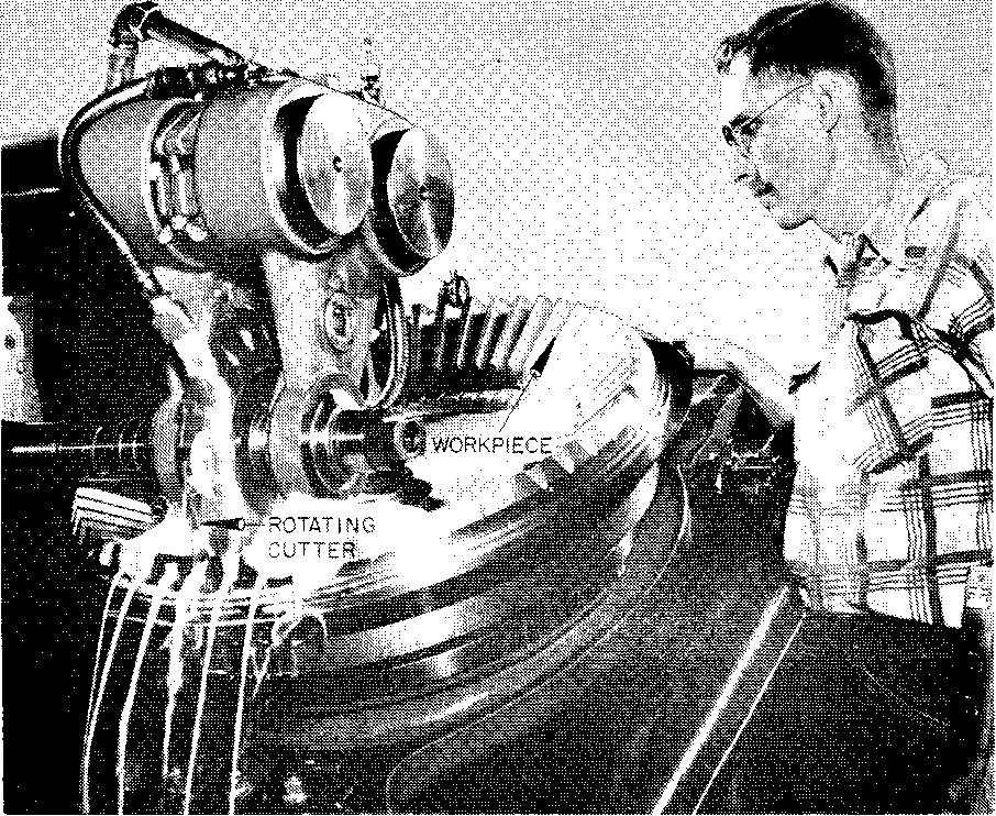
In this case, the ratio of their speeds would be 1:1 with no increase or decrease in speed. Miter gears are commercially available with a wide range of sizes. Bevel gears are designed in pairs and will only run with each other. Figure 19-15 shows how the teeth on a large bevel gear are produced.
fig. 19-15. Milling the teeth on a large bevel gear
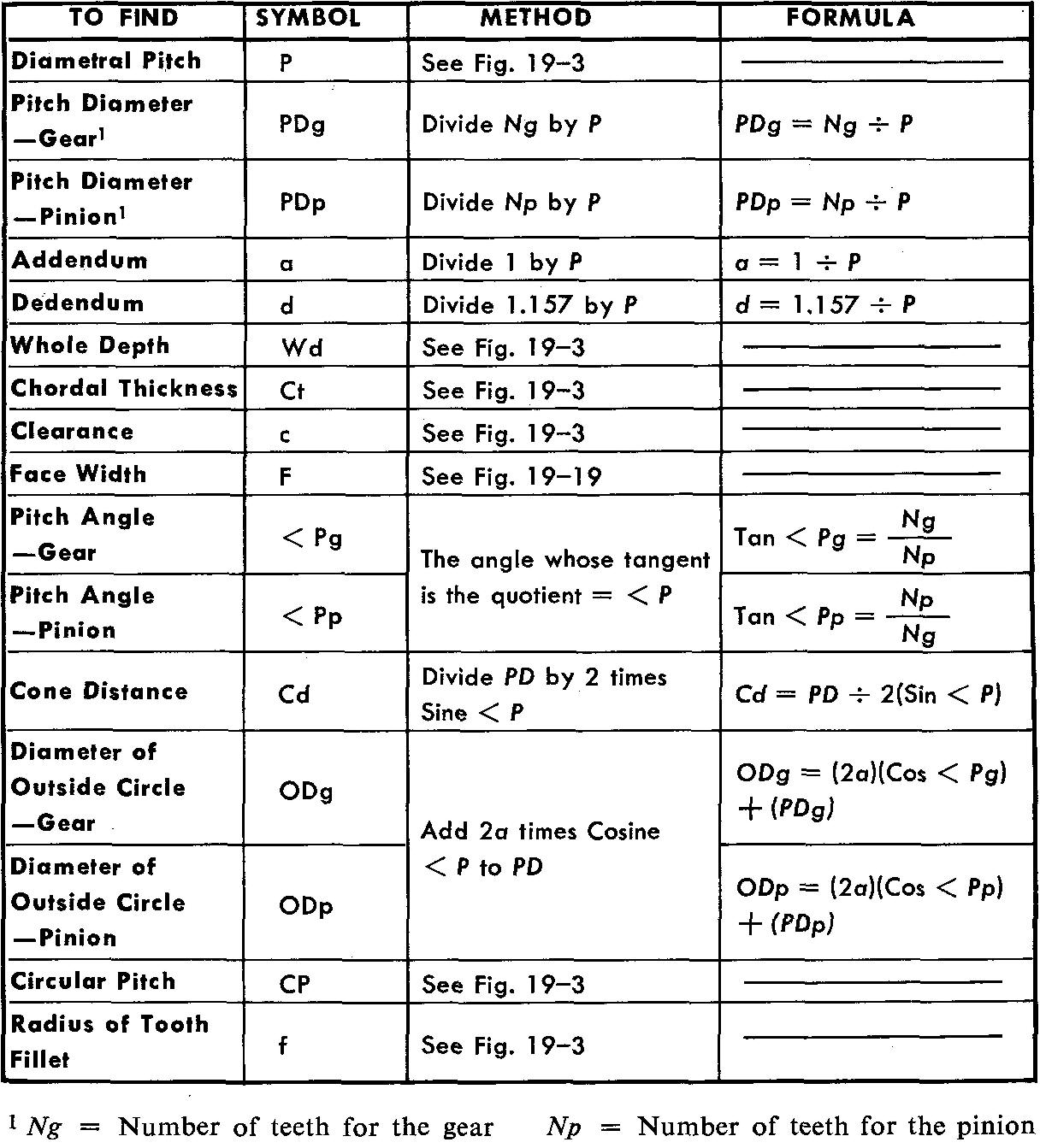
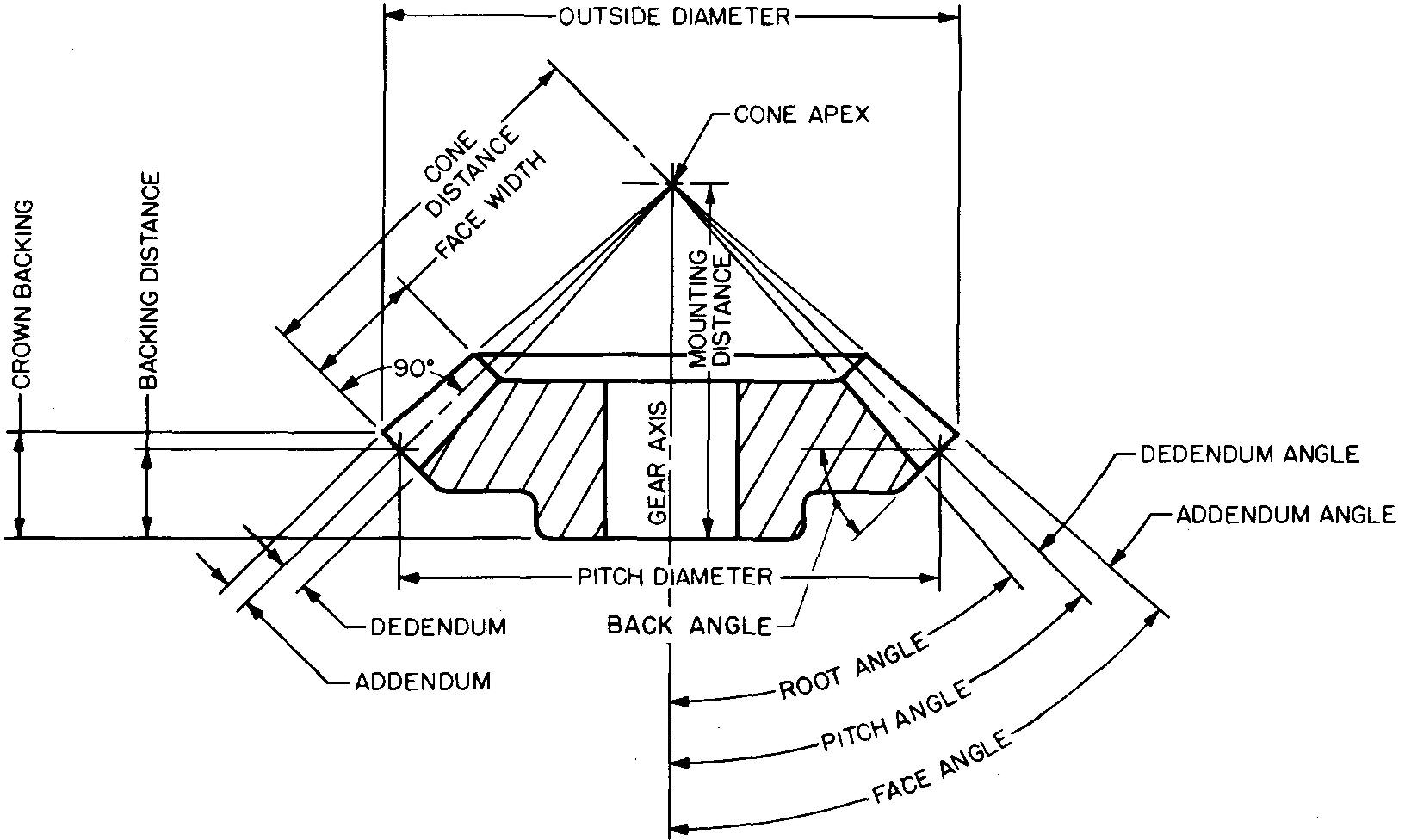
Bevel gear terms and formulas
Many of the terms used in spur gearing are used also for bevel gearing. There are several additional terms which are used only for bevel gears. Values of dimensions for bevel gears must also be worked out.
Figure 19-16 lists the various terms and formulas to use when working with bevel gears.
fig. 19-16. Bevel gear terms and formulas
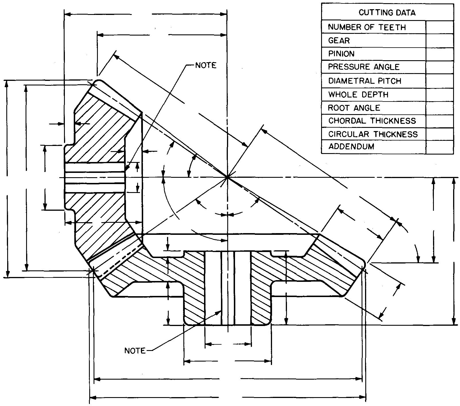
Detail drawings for bevel gears
Industrial practices vary somewhat in the requirements for preparing detail drawings of bevel gears. The gear and pinion may be drawn separately or they may be drawn together with the teeth engaged. In either case, only one view of each gear is generally drawn, and then as a full section.
When the gears are cast, as an aid to the patternmaker, the tooth curves are usually shown. When the gear teeth are to be cut, the tooth curves may be omitted on the drawing. Dimensions for the gear blank and the cutting data are placed on the drawing as in Fig. 19-17.
fig. 19-17. Detail views of a bevel gear
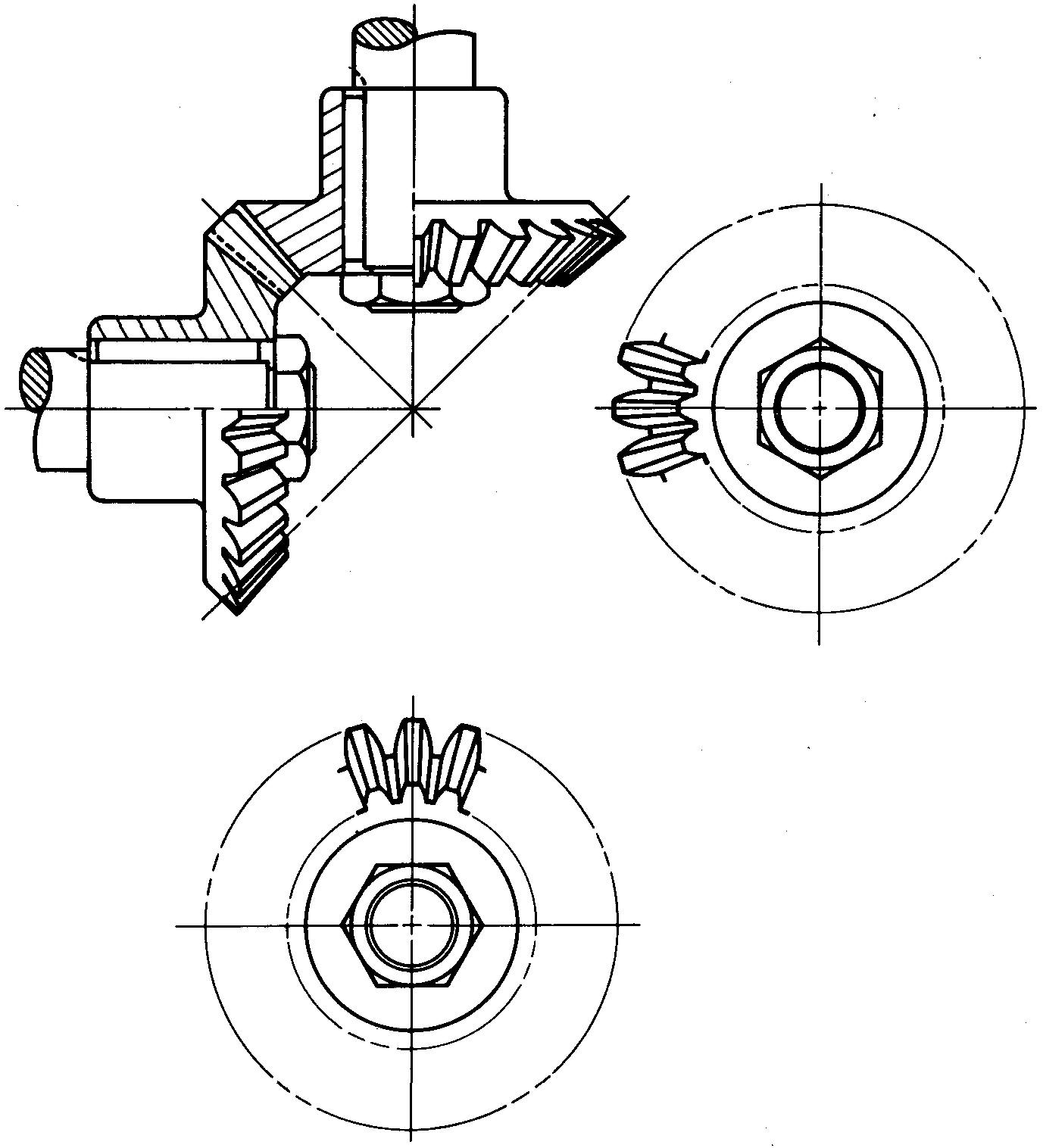
Assembly drawings for bevel gears
For assembly or display drawings, the gears are shown in mesh. Two views are usually drawn. All or just a few of the teeth may be shown, depending upon company standards. Figure 19-18 shows a method of representing bevel gears on assembly drawings.
fig. 19-18. assembly views of a bevel gear and pinion
Other bevel gear features
General proportions of the features of bevel gears have been worked out similarly to the features for spur gears. Figure 19-19 shows examples of common empirical formulas used by machine draftsmen. Some of the values may be adjusted slightly to fit existing conditions.
fig. 19-19. suggested proportions for bevel gear features
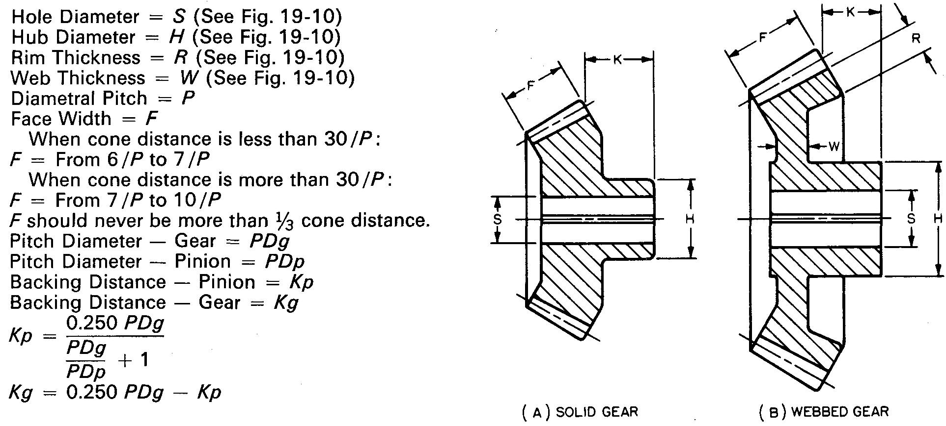
Two examples of sectional views for bevel gears are given, showing solid and webbed bevel gears. Suggested proportions for the features are given in the tables to the right of the drawings of the gears. Note that many proportions are found in Fig. 19-10.
Example
Make an assembly drawing of a bevel gear and pinion.
Specifications
Pressure angle = 14-1/2°, diametral pitch = 5, number of teeth for gear = 20, and number of teeth for pinion =16.
Solid gear and pinion.
Procedure
1. Refer to Figs. 19-3 and 19-16 and calculate the following dimensions:
a. Diameter of pitch
circle—gear.
b. Diameter of pitch circle—pinion.
c. Diameter of outside
circle—gear.
d. Diameter of outside circle—pinion.
e. Dedendum.
f.
Addendum.
Draw the pitch cones as shown in Fig. 19-20A and as described in steps 2 through 4.
fig. 19-20. layout of bevel gears
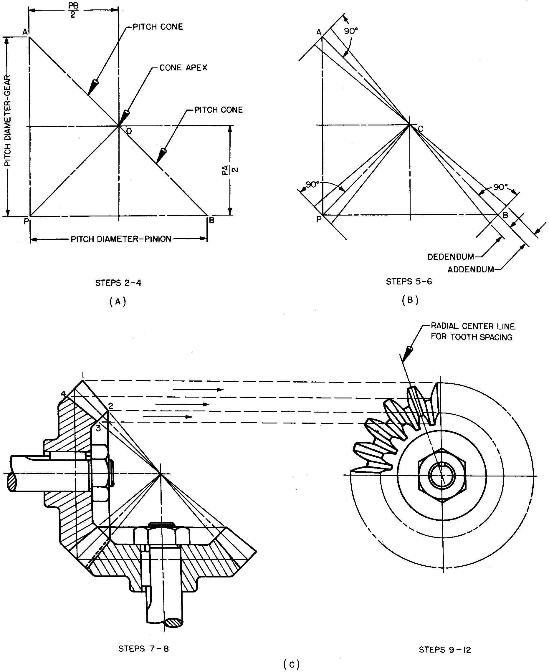
2. Draw the main center lines at right angles to each other to intersect at point 0, the cone apex.
3. Lay off the pitch diameters of the gear (PA) and the pinion (PB). Point P may be conveniently located by noting the dimensions PS/2 and PA/2.
4. Draw lines (called elements) OA, OP, and OB, which form the pitch cones.
Draw the addendum and dedendum as shown in Fig. 19-20B and as described in steps 5 and 6.
5. Draw lines at A, P, and B perpendicular to the elements drawn in step 4.
6. Lay off the addendum and dedendum distances and draw light elements to intersect at point 0.
Complete the drawing as shown in Fig. 19-20C and as described in steps 7 and 8.
7. Lay off the length of face for both the gear and the pinion, measuring along the pitch cone.
8. Work out the values for the
suggested proportions for the remaining features for both the gear and the
pinion as given in Fig. 19-19. Complete the full sectional view as shown.
If
one or both circular views are required, draw the views as shown in Fig. 19-20C
and as described in steps 9 through 12.
9. Establish the position for the center of the circular view. Lay off the main center lines. Project points 1, 2, 3, and 4 from the front view to the circular view and swing light circles.
10. Lay off the radial center lines for each tooth. (The tooth spacing equals 360°/N.)
11. Complete the circular view. Use an irregular curve to draw the approximate tooth curves. The sides of each tooth are radial.
12. Draw the views of the nut and the circles representing the end of the shaft.
Worm gears
These gears are widely used because of the many advantages obtained by their tooth action and load carrying capacities. Worm gears, Fig. 19-2C, transmit motion between two shafts.
The shafts are usually at right angles to each other but do not lie in the same plane. The teeth on the worm slide against the teeth of the worm gear, producing a rolling action. The worm gear cannot turn the worm. Thus, worm gears are said to be self-locking. Engineers use this principle to good advantage by installing worm gears in steering mechanisms, hoisting machinery, and so on.
Worm gear drives are quiet, vibration free, and extremely compact. The worm usually has from one to six threads. It is similar in form to the Acme screw thread. It may be made with either right-hand or left-hand threads, depending upon the desired direction of rotation of the worm gear.
Worms are made with single, double, or triple threads. Worms with single threads advance the worm gear a distance equal to the pitch for each complete worm rotation. The distance advanced is called the lead. Thus, the pitch equals the lead for a single thread.
Worms with double threads advance the worm gear twice the pitch for each complete rotation of the worm. Worms with triple threads advance the worm gear three times the pitch. Our studies will deal with the single thread worm only.
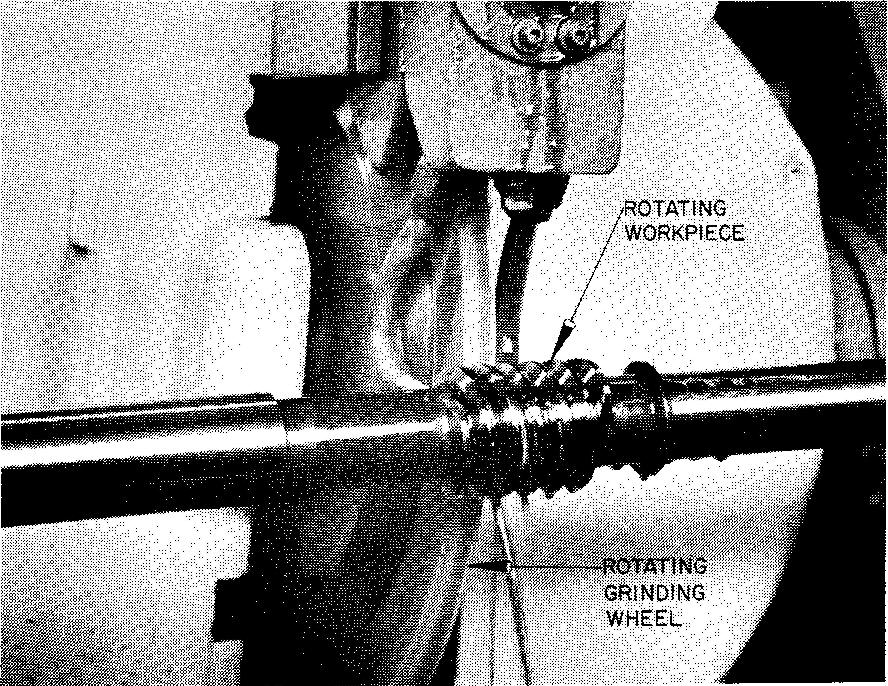
Worm gear threads may be produced by the method shown in Fig. 19-21 and finished by grinding as shown in Fig. 19-22.
fig. 19-21. Rolling a worm thread
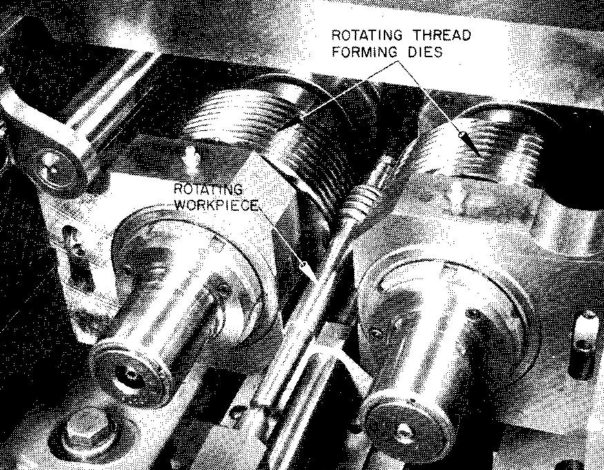
fig. 19-22. Grinding a worm thread
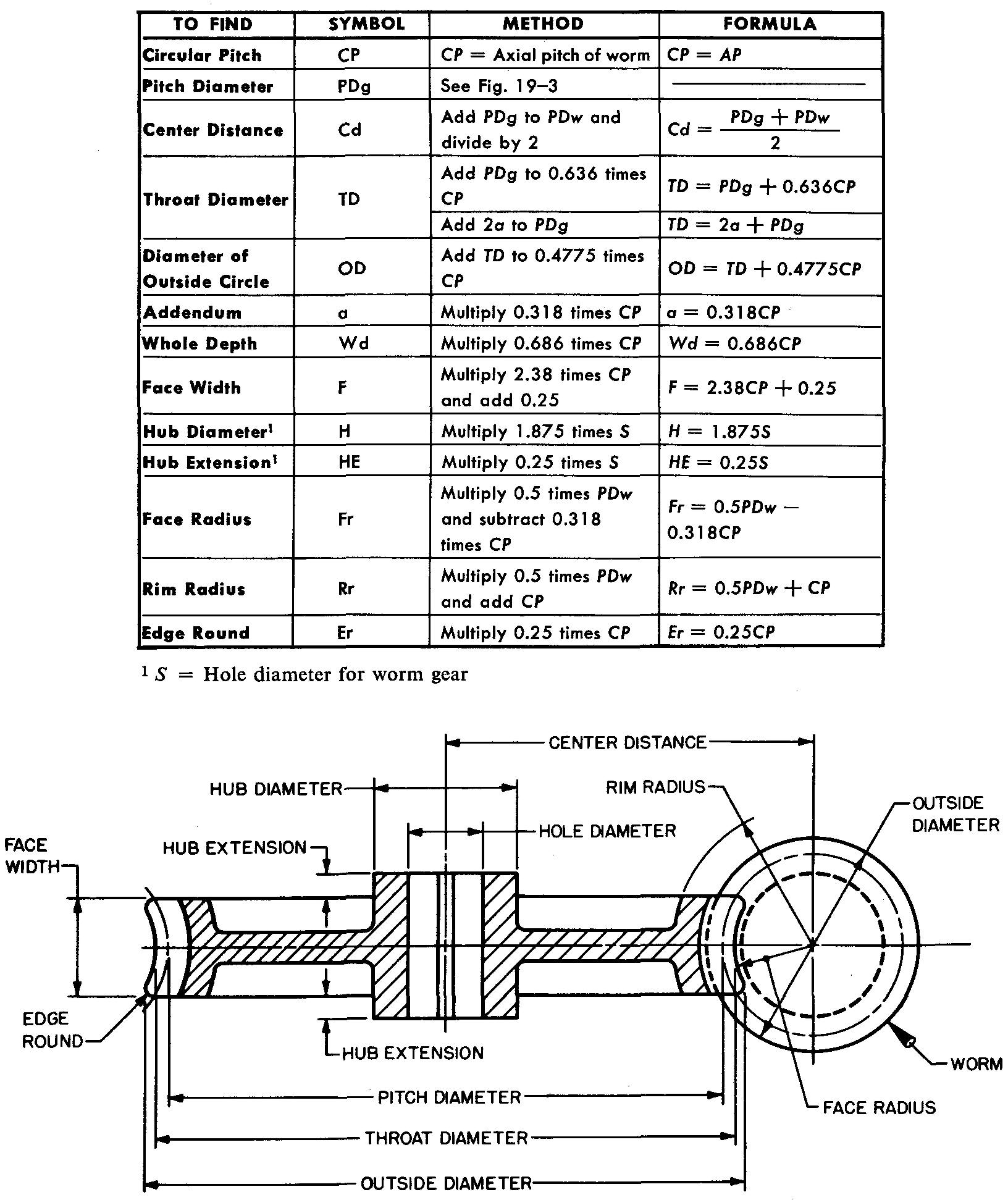
Worm gear terms and formulas
Many of the terms and calculations used in worm gearing are the same as those used for spur gears. However, there are several additional terms used only for worm gears.
Figure 19-23 illustrates terms and formulas for the worm and Fig. 19-24 illustrates those for the worm gear.
fig. 19-23. Worm terms and formulas
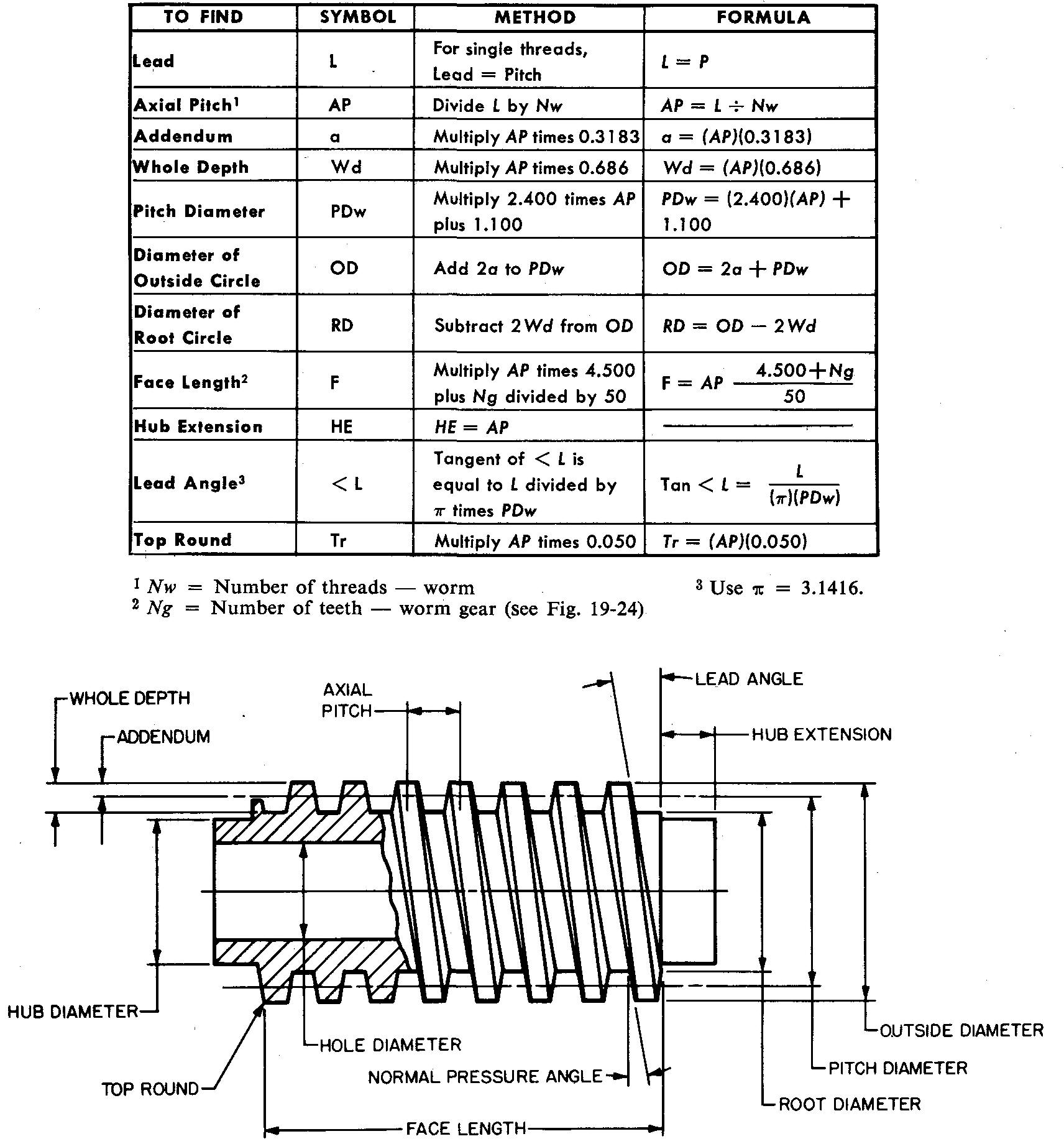
fig. 19-24. Worm gear terms and formulas
Detail drawings for worms and worm gears
These detail drawings generally show each part drawn separately. Figure 19-25 shows a detail drawing of a worm gear. The tooth curves in the circular view are not drawn.
fig. 19-25. Detail views of a worm gear
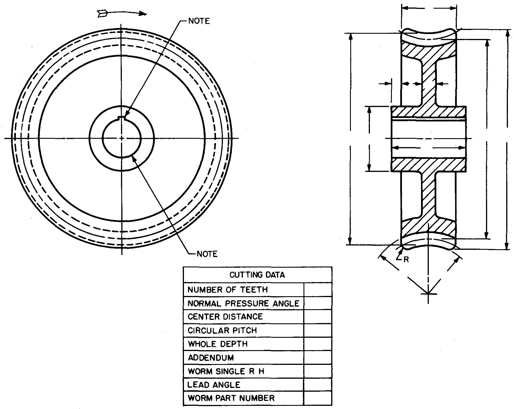
Instead, the teeth are represented by drawing the outside tooth circle, the pitch circle, and the root circle. The method of representing the circular view of the worm gear is the same as for the spur gear. Note the arrow which is used to show the direction of rotation. The side view is drawn as a full section.
The gearstead, the teeth are represented by drawing the outside tooth circle, the pitch circle, and the root circle. The method of representing the circular view of the worm gear is the same as for the spur gear. Note the arrow which is used to show the direction of rotation. The side view is drawn as a full section.
The gear blank dimensions are given on the views, and the cutting data are listed in the table.
Figure 19-26 shows a detail drawing of a worm.
fig. 19-26. Detail views of a worm
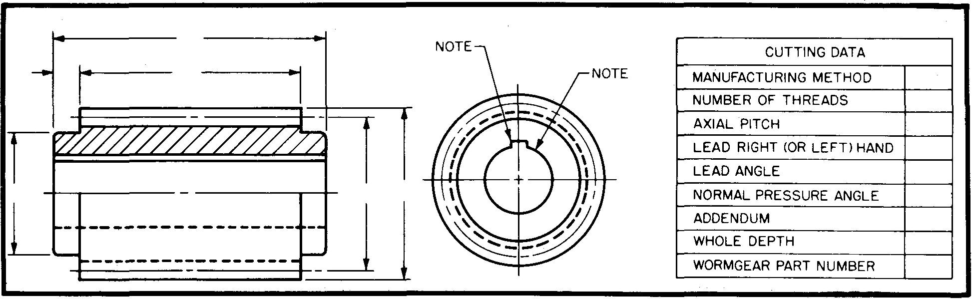
The front view may be drawn to represent the worm blank as shown. Another method, preferred by some companies, is to draw the worm as in Fig. 19-23. In this case, the method for drawing the teeth is the same as the method for drawing a detailed representation for screw threads. Dimensions are given on the views, and the cutting data in the table.
Assembly drawings for worms and worm gears
Assembly drawings are drawn as in Fig. 19-27.
fig. 19-27. Assembly views of a worm and worm gear
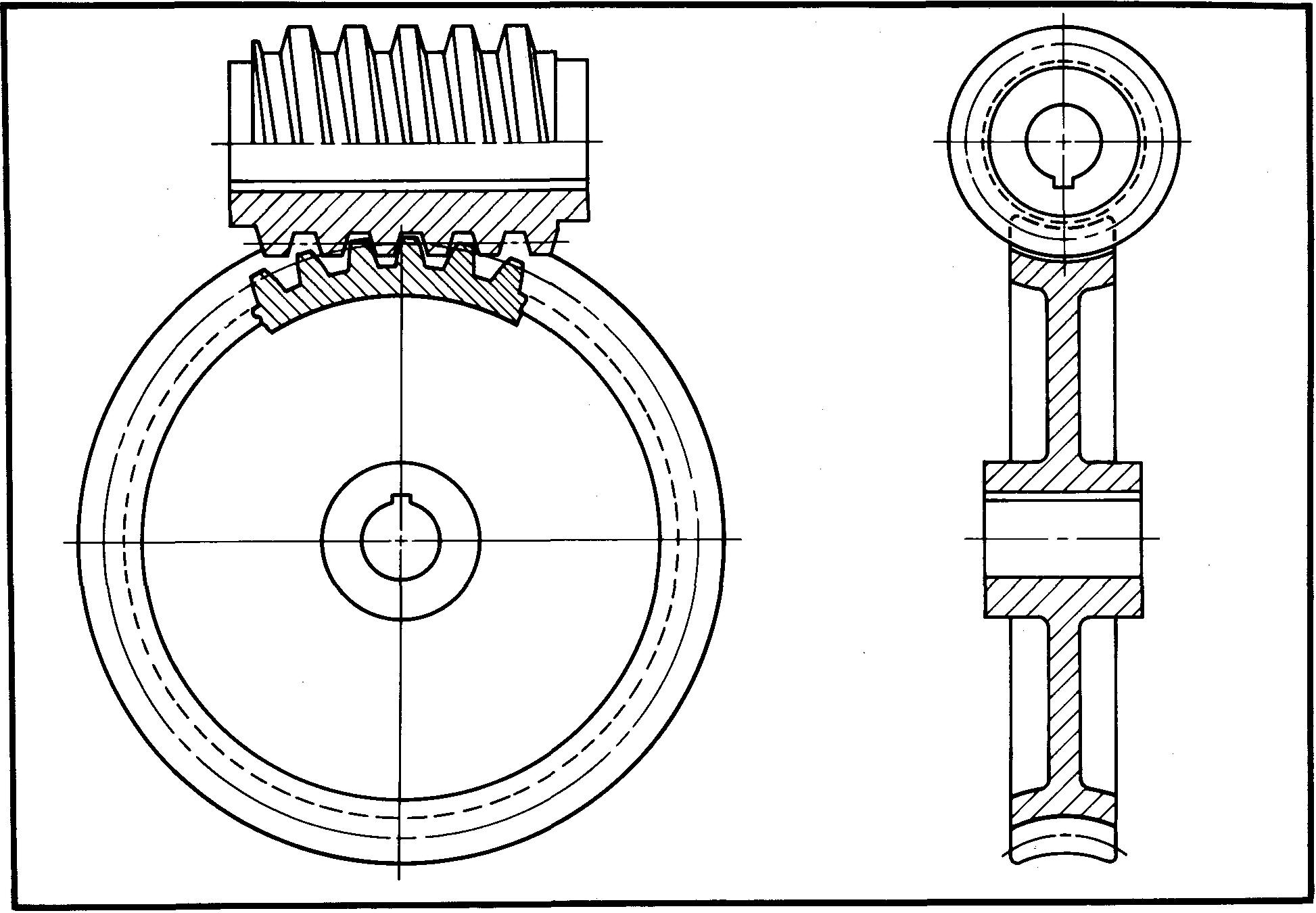
The teeth are usually shown engaged. A broken-out section is drawn to show the
teeth in the circular view of the worm gear. A half section is made for the worm.
Example
Make an assembly drawing of the worm and worm gear.
Specifications
Pressure angle = 14-1/2°, pitch = 0.625 inch, number of threads for worm = 6, and number of teeth for worm gear = 38.
Procedure
1. Refer to Fig. 19-23 and calculate the following dimensions for the worm:
a. Addendum.
b. Whole depth.
c. Diameter of pitch circle.
d. Diameter of outside circle.
e. Face
length.
f. Hub extension.
g- Hole diameter.
h. Lead angle.
i. Top
round.
Refer to Fig. 19-24 and calculate the following dimensions for the worm gear:
a. Diameter of pitch circle.
b. Center distance.
c. Throat diameter.
d. Diameter of outside circle.
e. Whole depth.
f. Face width.
g. Hub diameter, h. Hub extension.
1.
Face radius, j. Rim radius, k. Edge round.
Prepare the assembly drawing as shown in Fig. 19-27 and as described in steps 2 through 8.
2. Lay off the main center lines for both views and establish the center distance.
3. Swing the pitch circles of both the worm and the worm gear. The circles will intersect at the pitch point.
4. With the compass set to the face and rim radii, swing arcs.
5. Swing the outside and the root circles.
6. In the circular view, starting at the pitch point, draw the tooth outline of the worm.
7. Also in the circular view, draw four or five gear teeth. (See Sec. 19-12, Example 2.)
8. Complete the views by drawing in all the other features, such as the hole diameter, hub diameter, hub length, the web, the key, and the keyway.
Review questions (The answers are not given)
1. What two mechanical changes do gears provide?
2. What is meant by the speed ratio of two mating gears?
3. What is the purpose of teeth on gears?
4. How is the gear distinguished from the pinion?
5. How is speed affected when a smaller gear drives a larger one?
6. List three kinds of metals and three kinds of nonmetals used in gears.
7. What is the relationship of the position of one shaft to the other for mating spur gears?
8. Define a gear blank.
9. On a detail drawing, what method is use; to give the size information pertaining t the gear blank?
10. What is meant by cutting data? Where if this information given on a detail drawing?
11. Would it be necessary to finish the teeth on spur gears which are rough cast tc shape? Explain.
12. On assembly drawings, the tooth curves of spur gears may be entirely omitted Name the circles which are drawn to represent the omitted teeth.
13. An empirical formula is considered:
a. Very accurate.
b.
Reasonably accurate.
c. A very rough approximation.
14. What feature of a gear may be designed to reduce the weight?
15. What circle (used in drawing gear teeth) may be found by laying out the pressure angle?
16. Which gear tooth is considered stronger, one with a 20° pressure angle or one with a 14-1/2° pressure angle? Explain.
17. What necessary information for drawing gear teeth may be obtained by using Grant's Involute Odontograph Tables?
18. Which radius (used in drawing gear teeth) gives the curve of the tooth above the pitch circle?
19. What is the size of the tooth curve radius when the single curve method is used?
20. What is the relationship of the position of one shaft to the other for bevel gears?
21. Under what conditions may gears be referred to as miter gears?
22. For detail drawings of bevel gears, what kind of sectional view is recommended?
23. Why are the tooth curves usually drawn when the gear teeth are cast to rough shape?
24. Define the lines called elements which are used in drawing bevel gears.
25. Define perpendicular.
26. What relationship does the pitch have to the lead for a double thread?
27. In a worm gear system, which of the two is the driving gear?
28. For worm gears, what is the relationship of the position of one shaft to the position of the other shaft?
Problems
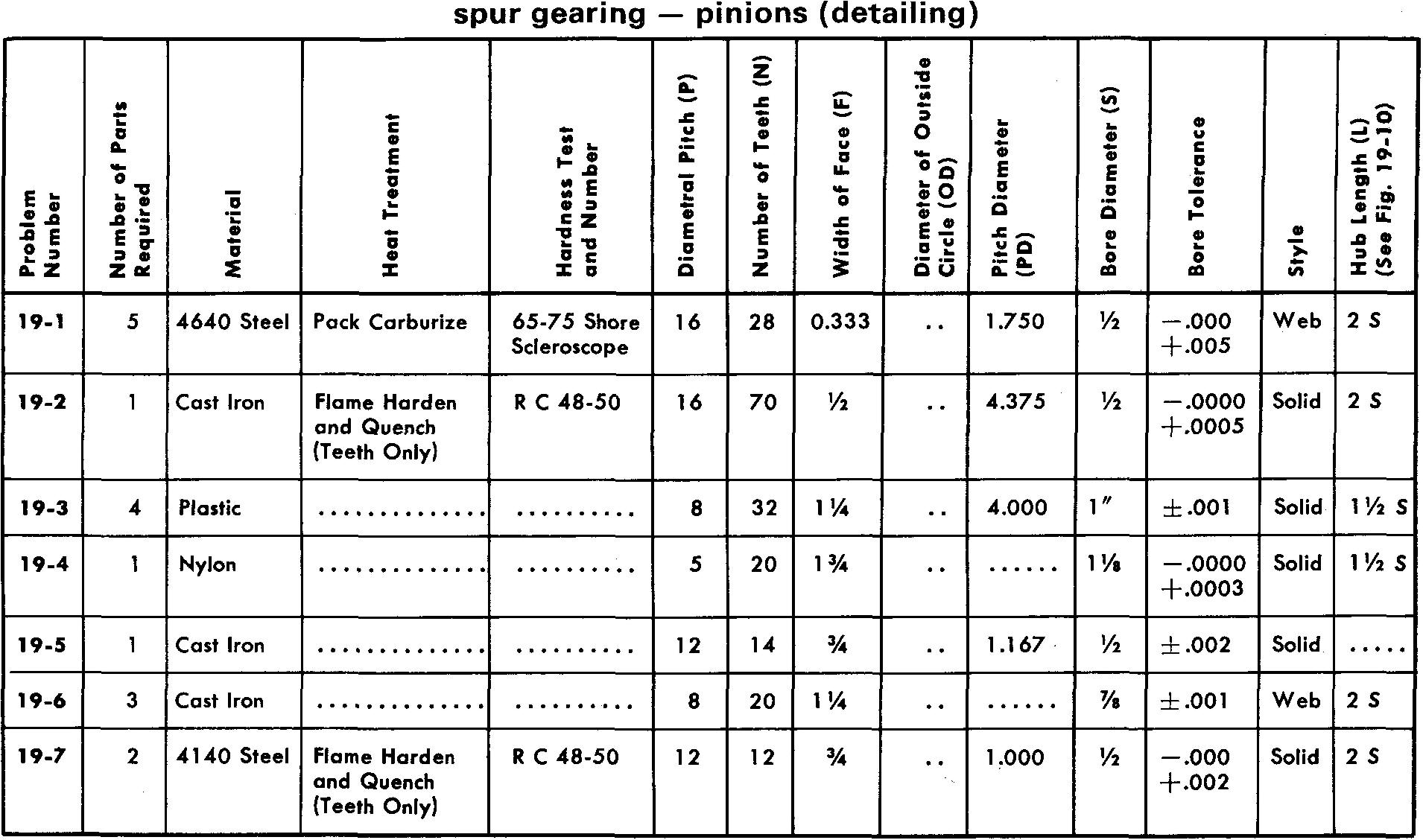
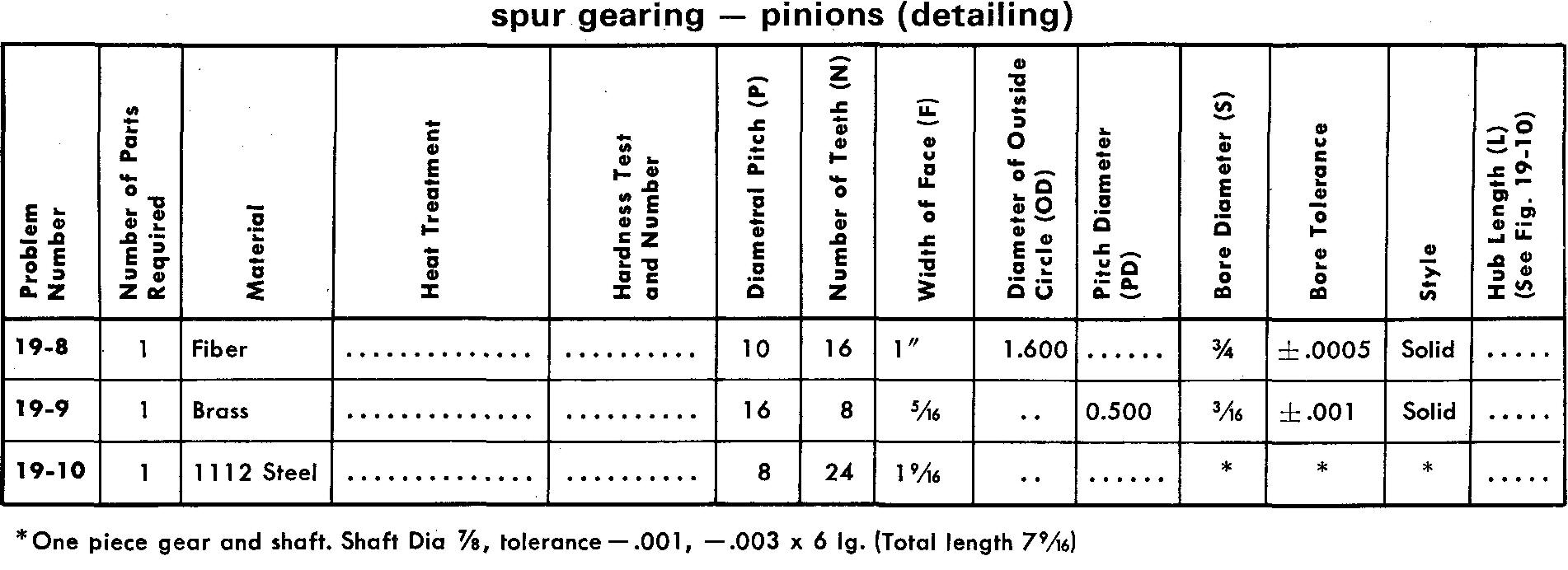
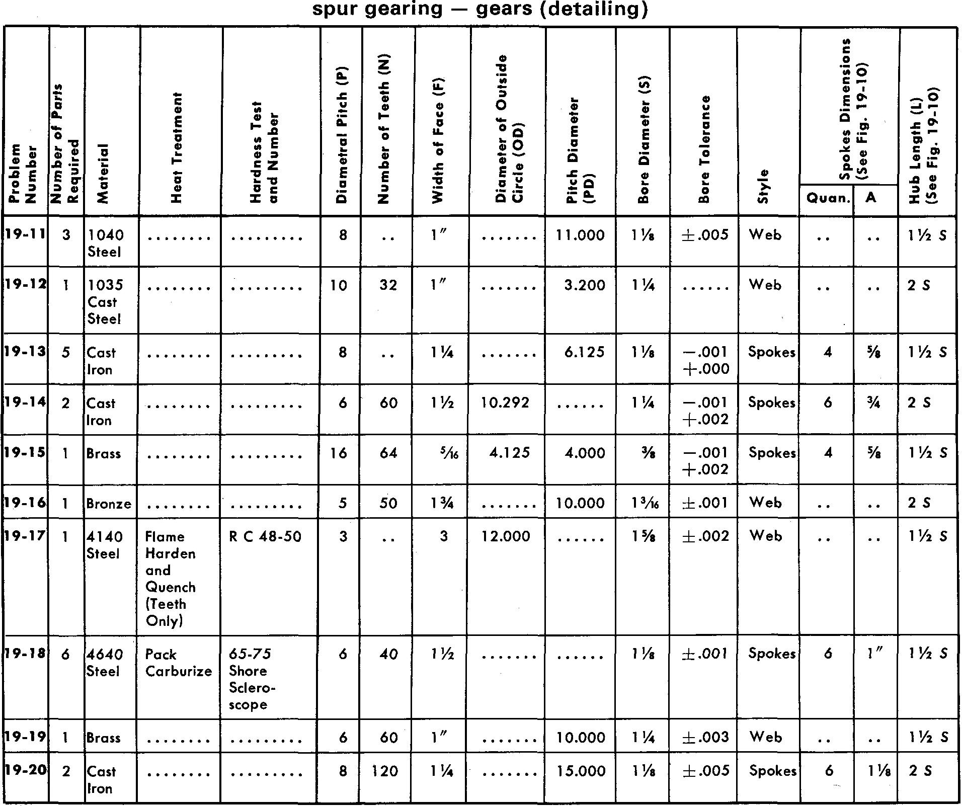
Problems 19-1 through 19-20 pinions and gears
Prepare detail drawings according to the listed specifications.
For Problems 19-3, 19-5, 19-10, 19-12, 19-19-15, and 19-19, draw 3 or 4 teeth, as shown in Fig. 19-7, using either the Single Curve Method or Grant's Involute Odontograph Tables as assigned by your instructor.
Use the method shown in Fig. 19-6 for all other problems.
Refer to Fig. 19-10 for suggested proportions of features for pinions and gears.
Estimate the proportions of the spoke tapers.
Make all necessary calculations, using the table in Fig. 19-3, and place the appropriate data in a cutting table or in the form of dimensions and notes on the drawing.
Use either a Square key or a Pratt and Whitney key and a 14-1/2° pressure angle for all problems.
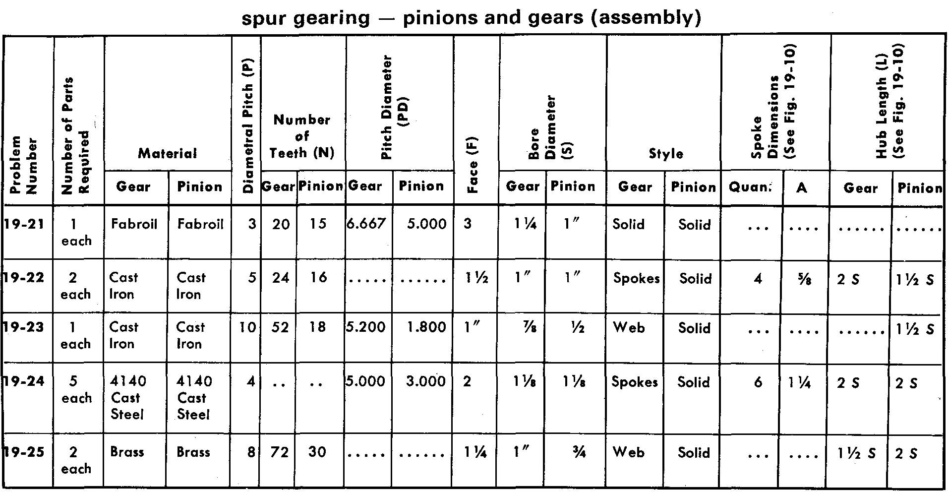
problems 19-21 through 19-25 pinions and gears
Prepare assembly drawings similar to Figs. 19-8 or 19-9 according to the specifications.
Assume the tolerance on all bores to be -0.001, +0.002. Use a Square key or Pratt and Whitney key and a 14-1/2° pressure angle for all problems.
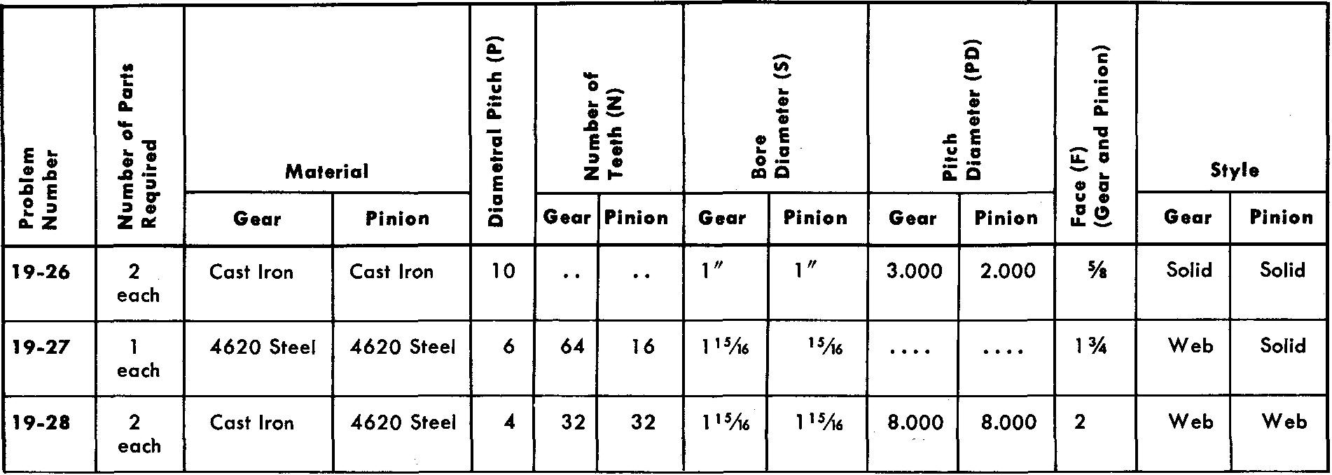
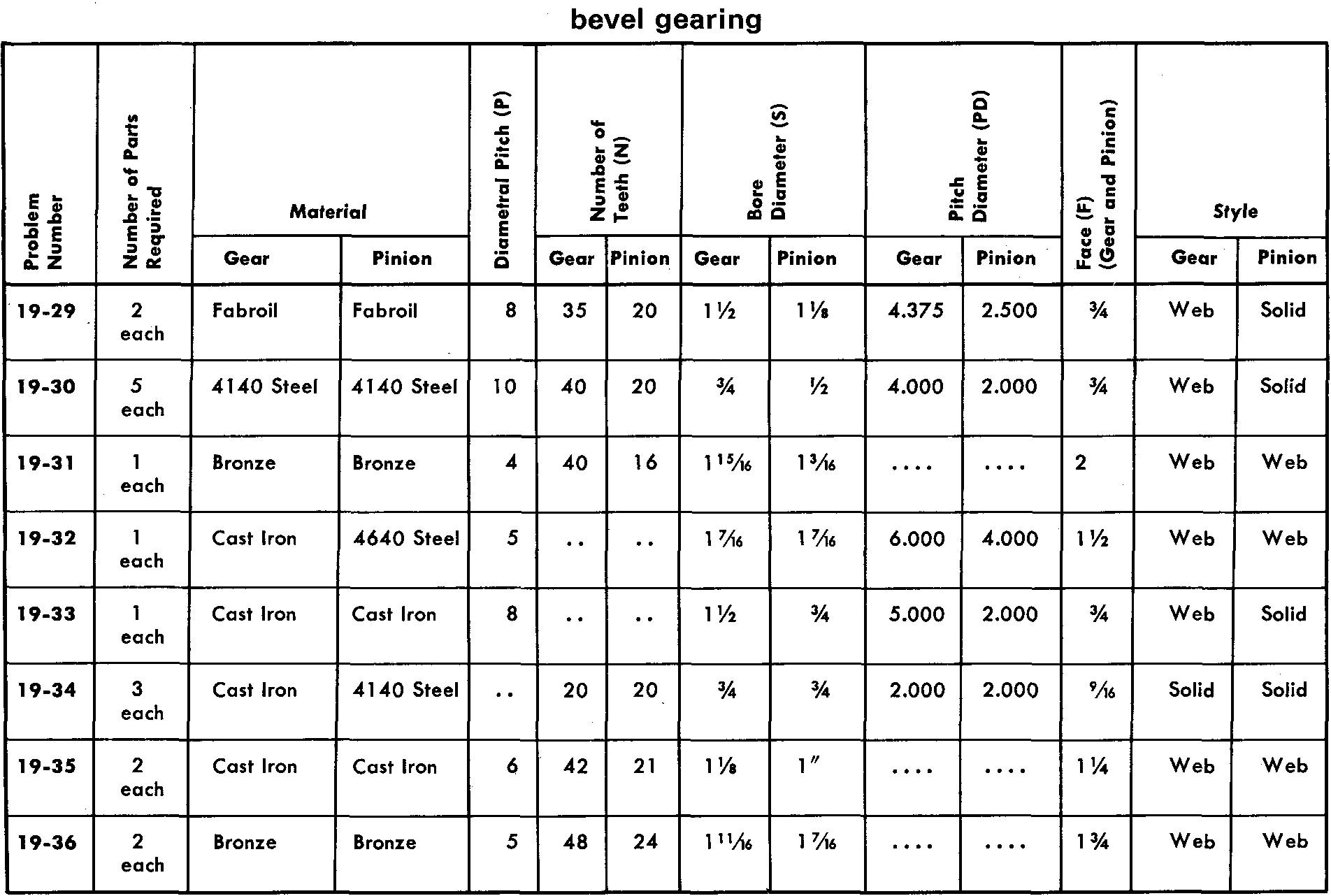
problems 19-26 through 19-36 bevel gearing
Prepare detail or assembly drawings as assigned by your instructor according to the listed specifications. Refer to Fig. 19-16 and Fig. 19-19.
Where a heat treatment is required use Pack Carburizing to a Shore Scleroscope hardness value of 75-85. Estimate all omitted dimensions. The pressure angle is 14-1/2°.
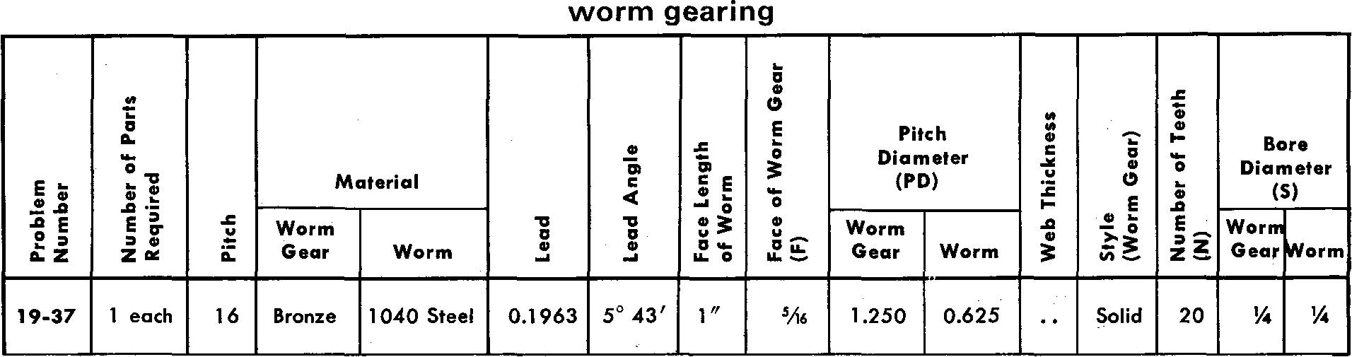
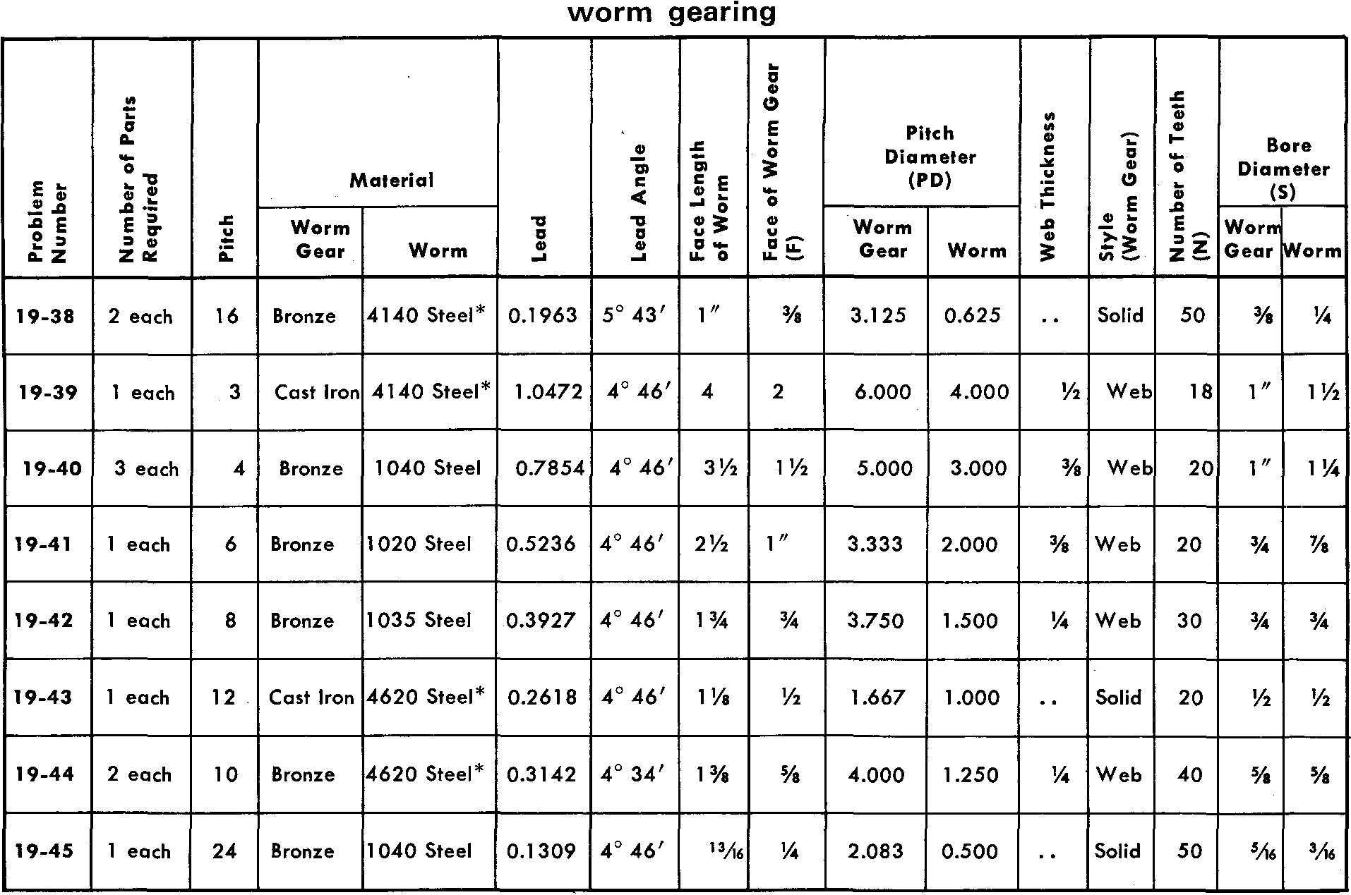
Problems 19-37 through 19-45 worm gearing
Prepare detail or assembly drawings as assigned by your instructor according to the listed specifications. Refer to Fig. 19-23 and Fig. 19-24 for calculations.
Worms identified in the table with an asterisk (*) are to be heat-treated. AISI steel 4140 is to be induction hardened to Rockwell C hardness value 48-52. AISI steel 4620 is to be pack car-burized to a Shore Sceleroscope hardness value of 68-75.
Estimate all omitted dimensions.
Keys should be installed for gears and worms having bores of 1 /2 inch or more. Gears and worms with bores of less than 1 /2 inch should have hubs for installing headless set screws.
The pressure angle is 14-1/2°
![]()