Principles of cam drawings
Introduction
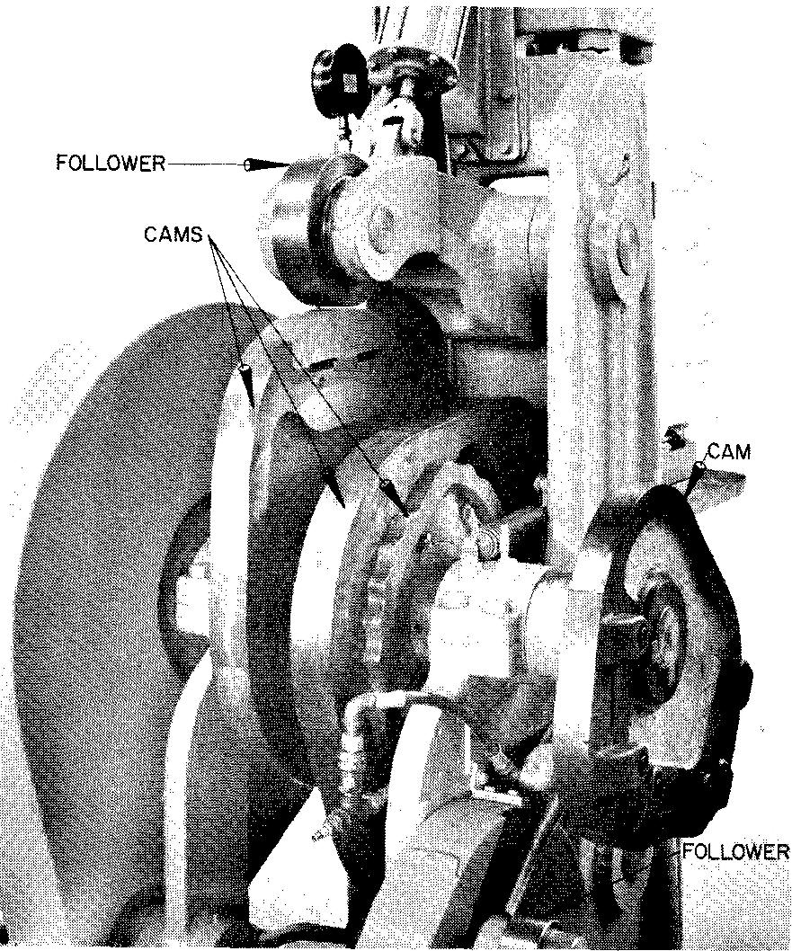
A rotary cam, Fig. 18-1, is a part on a machine which mechanically changes cylindrical motion to straight-line motion.
fig. 18-1. Cams
The cam, which is mounted on a shaft, is usually driven by a motor either applied directly to the cam shaft or connected by pulleys or gears. The purpose of a cam is to transmit various kinds of motion to other parts of a machine. T
he cams on a machine for stitching shoes, for example, change the rotation of the motor spindle to the irregular or up and down action which is required for stitching leather. Cams are considered the best means of producing a wide variety of different motions.
Practically every cam must be designed and manufactured to fit special requirements. Cams are seldom purchased as a catalog item. In general, cams are custom made. Thus, it is almost certain that a machine draftsman will be called upon to make the working drawings of a cam.
Cams are used on linotype machines, gasoline engines, printing presses, textile machines, metal shapers, shoe machinery, stamping machines, feed mechanisms for production machines, and, in fact, on practically all kinds of automatic machinery.
How cams work
Though each example in Fig. 18-2 appears to be quite different, all the cams work in a similar way.
fig. 18-2. Examples of commonly used cams
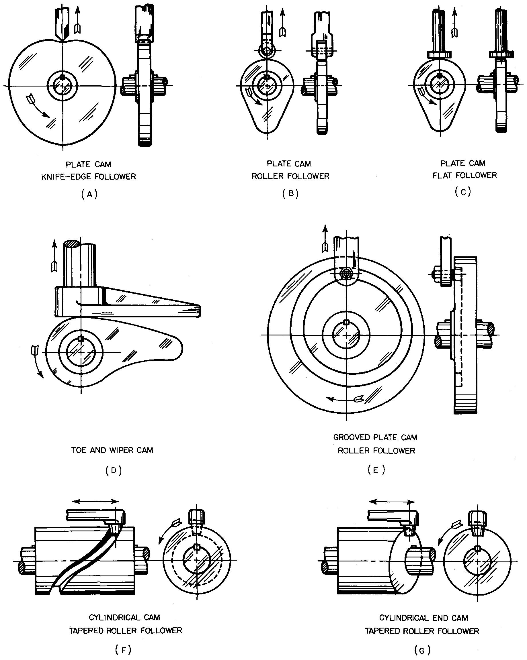
In each case, as the cam is rotated or turned, another part in contact with the cam, called a follower, is moved either left and right, up and down, or in and out. The follower is usually connected to other parts on the machine (not shown in Fig. 18-2) to accomplish the desired action.
The direction the follower moves depends upon the position of the framework which attaches the cam and follower to the machine. In Fig. 18-2 A through D, the cam consists of an irregularly shaped metal plate.
Note the different kinds of
followers illustrated. In these examples, as the cam rotates, the follower moves
up and down. It is held in contact with the cam edge either by its own weight or
by a spring. If the follower loses contact with the cam, it will fail to work.
In Fig. 18-2 E and F, cams with grooves are shown. The follower cannot lose contact with cams of this type, since the follower works in the groove and is held in place by the groove.
A follower which is in contact with a cylindrical end cam is shown in Fig. 18-2G. As the cam rotates, the follower is caused to move left and right.
The faster the cam turns, the more rapid is the motion of the follower. The motion of the follower caused by rotating the cam is exactly the same for each complete turn of the cam. The same principle is involved for all cams.
Designing cams
In most companies, engineers or designers prepare the design layouts for cams. Design layouts may include specifications for velocity and acceleration, appropriate cam materials, machining requirements, and heat treatment. In addition, the design for the required follower for the cam system is worked out.
Basically, there are two steps involved in designing and drawing a cam.
step 1
Working out the displacement diagram, establishing the desired motion, and designing the cam and follower. The design engineer is usually responsible for this step for complicated motions.
step 2
Preparing the detail drawings of the cam and cam follower. The machine draftsman is responsible for this step.
The displacement diagram
Various kinds of motion or action may be transferred to the follower, depending upon the shape and type of the cam. The shape of the cam is determined by the displacement diagram which is usually made before any of the views of the cam are drawn.
A displacement diagram is a kind of graph which shows the timing and rate of speed of the follower during one complete cam rotation.
The term displacement diagram is used because it shows the amount the follower is displaced or moved from one position to another. The displacement diagram also shows the position or path of the follower at any given position as the cam rotates.
Figure 18-3 shows a displacement diagram. The length can be drawn to any convenient size, but it should represent one complete 360° rotation of the cam. The length is spaced off in degrees and represents the time for one revolution of the cam.
The height is spaced off in inches and is drawn full size to an accurate scale. The height represents the maximum or total rise (displacement) of the follower. We shall discuss the various spacings of the height in subsequent paragraphs. The rise is the total distance the follower is moved (or displaced) from the starting position through one complete turn of the cam.
From Fig. 18-3 we can determine the position of the follower at any interval or period of the cam rotation.
fig. 18-3. A displacement diagram
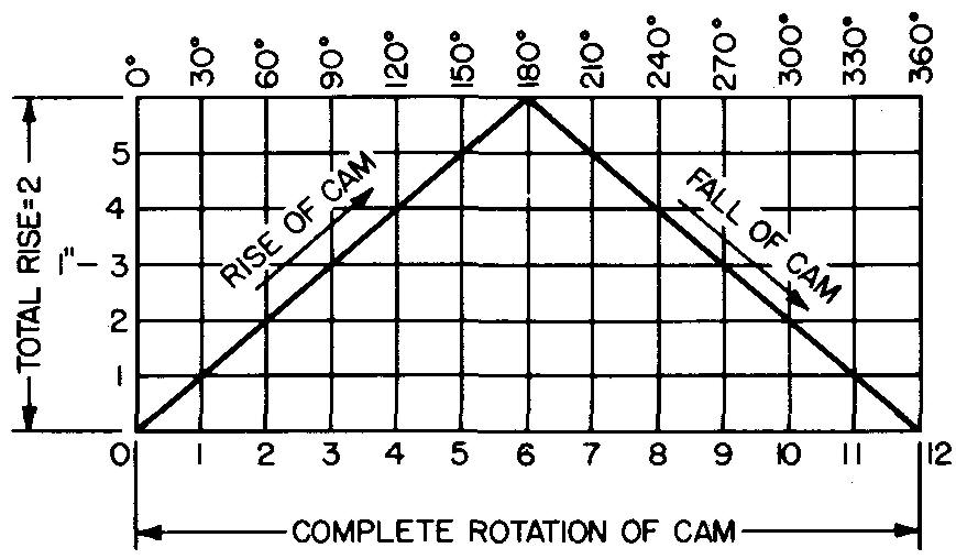
The follower starts at 0° and rises 1 inch in 90°, or one fourth of the cam rotation; at 180°, or one half of the cam rotation, its rise is at a maximum of 2 inches; at 270°, or three fourths of the cam rotation, it falls to 1 inch; and it finally returns to its original starting point at 0°.
From this graphic illustration we can determine the motion of the follower at any period through one complete turn of the cam (360°).
Cam motions
There are three standard types of cam motions in common use. A working knowledge of each is important. The design engineer decides upon the type of motion he will use after studying the requirements of the machine using the cam.
The displacement diagram for this type of motion is then made and the cam shape and size are worked out.
Uniform motion
Figure .18-4A shows half a displacement diagram for uniform motion.
fig. 18-4. Uniform and modified uniform motion
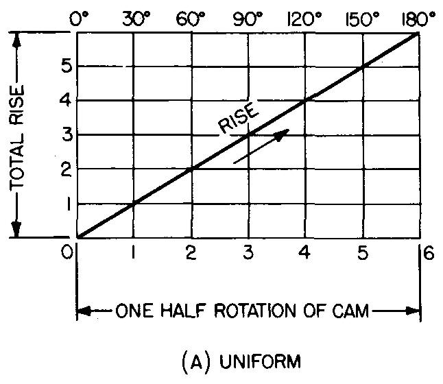
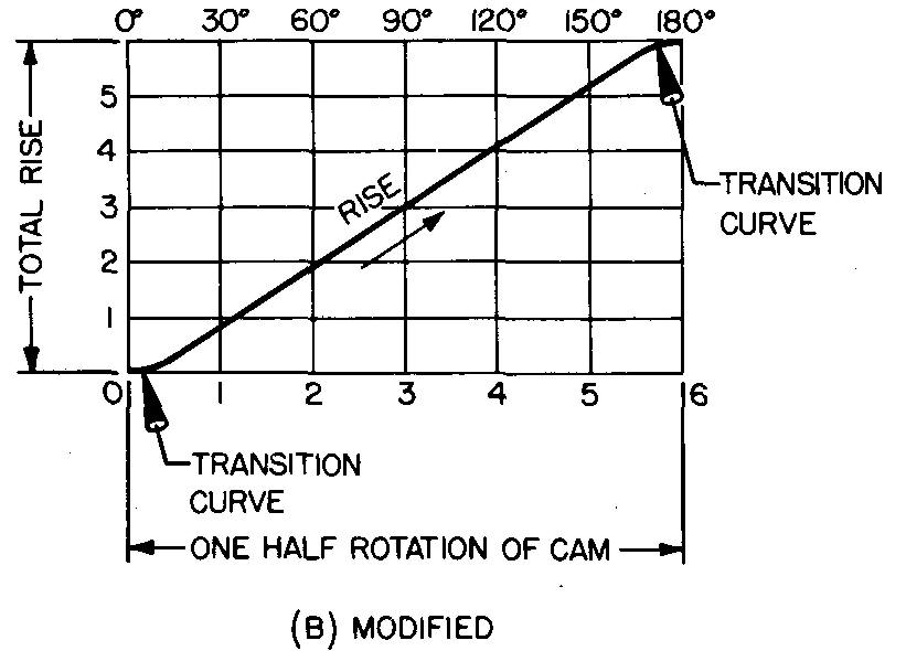
This motion is used when the mechanism can be designed to be sturdy and rigid enough to withstand the shock which is transmitted to the follower at the starting position. Here, the rate of speed is the same from the start to the stop positions. The action of the cam is rough and abrupt.
Engineers avoid using this type of motion whenever possible, preferring the curve shown in Fig. 18-4B. Here, the shocks at the start and the stop positions have been made less abrupt by using a transition curve.
A cam with this type of curve is said to have modified uniform motion. The cam is usually operated at relatively low speeds. Some machine operations require cams such as this which deliver motion to moving parts at a constant speed.
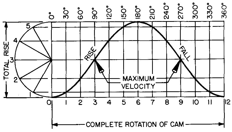
Simple harmonic motion
This motion, shown in Fig. 18-5, is used when uniformity of motion is not especially essential and when a smooth start and stop are desired, as in feed mechanisms. It is also used where high speeds are necessary.
One revolution of the cam produces maximum velocity at 90°, zero velocity at 180°, maximum velocity at 270°, and zero velocity at 360° (0°). Simple harmonic motion produces a smooth and easy follower action.
fig. 18-5. Harmonic motion
Constantly accelerated and decelerated motion
The motion shown in Fig. 18-6 results in a gradual increase and decrease in speed. The half of the curve from 0° to 90° is exactly the reverse of the half from 90° to 180°. At no time is the speed uniform. It is considered the smoothest of all three motions.
fig. 18-6. Constantly accelerated and decelerated motion
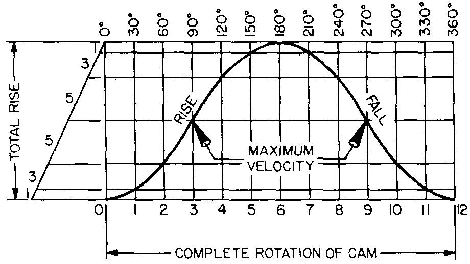
The basis for the motion is the same as for a free-falling body:
An object dropped from a high point would fall to the earth with a constant acceleration. In the same way as a free-falling body, the speed of the cam follower increases by equal amounts in equal intervals of time and decreases by equal amounts in equal intervals of time.
The follower speed is the greatest at 90° and the least at the top of the curve, 180°. The speed increases inversely on the fall and reaches a maximum at 270°.
Combination of motions
Any one of the three motions thus described may be used on a particular cam. The motions may also be combined to produce a variety of motions.
Subsequent examples show how a combination of motions may be used for any one cam design. One cam can combine uniform motion, simple harmonic motion and constantly accelerated and decelerated motion.
Cam models
As an aid in understanding how cams work, a cam model may be made. It is suggested that firm cardboard be used. The model may be made by placing a cam drawing such as Figs. 18-10, 18-13, or 18-16 over the cardboard.
Important points, such as the camshaft center and intersecting points formed by the radial lines and the cam edge working surface, may be transferred to the cardboard surface by pricking through the drawing with a sharp point.
The cam curve is made by connecting the points thus located on the cardboard and cutting around the curve. Next, a small piece of cardboard should be cut, resembling the type of follower desired.
Assemble the pieces as shown in Fig. 18-7 by fastening the cam cutout and follower to a drawing board. The cam cutout may now be rotated in contact with the follower.
fig. 18-7. A working model of a cam
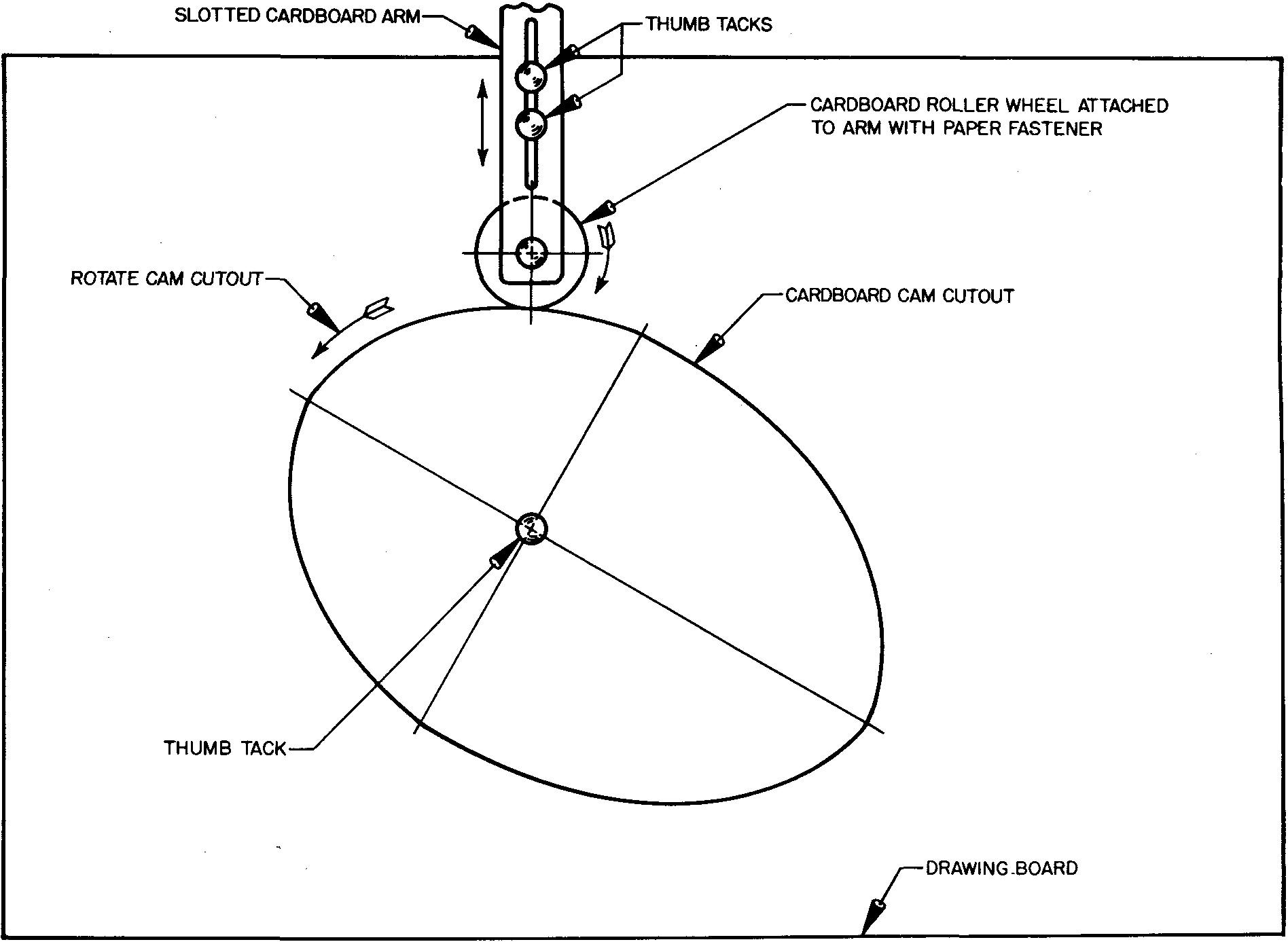
The model will be suitable for examining what actually happens when a cam is rotated in contact with a follower. Study carefully the action of the follower as the cam is rotated.
Examples of cam motions
The following examples illustrate the procedure for drawing the displacement diagram and the required views of various cam forms and followers.
Example 1. modified uniform motion
This is the method a machine draftsman uses to draw a radial plate cam with modified uniform motion.
Requirements
Assume a knife-edge follower is to rise 1-1/2 inches with modified uniform motion in 180° and fall 1-1/2 inches with the same motion in 180°. The rotation of the cam is counterclockwise.
Procedure
PART I:
Draw the displacement diagram as shown in Fig. 18-8, and as described in steps 1 through 6.
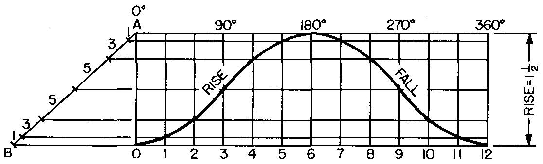
fig. 18-8. Displacement diagram : cam with modified uniform motion
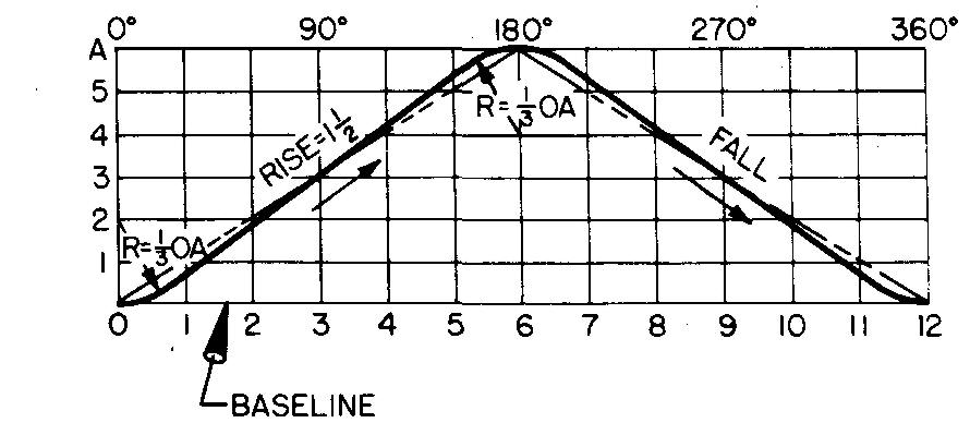
1. Lay off the rise 0-A equal to the maximum rise of the follower (1-1/2 inches).
2. Lay off the base line 0-12 equal to any convenient distance.
3. Mark the midpoint 6 on line 0-12 and divide both 0-6 and 6-12 into 6 equal divisions. Each division will be equal to 30° of cam rotation. Draw vertical lines through these points.
4. Divide the rise 0-A into the same number of divisions as 0-6 (in this case, 6 divisions). Draw horizontal lines through these points.
5. With a radius equal to 1/3 OA, draw the arcs as shown. While there are other methods used to draw the arcs for the transition curve, R = 1/3 OA is considered accurate enough for most purposes. (For graph work, even though a straight line is used, it is called a curve.)
6. Draw straight lines tangent to the arcs, which will complete the displacement diagram with the required modified uniform motion curve.
PART II:
Draw the views of a radial plate cam, as shown in Figs. 18-9 and 18-10, and as described in steps 1 through 4 and 5 and 6.
fig. 18-9. Layout of a radial plate cam
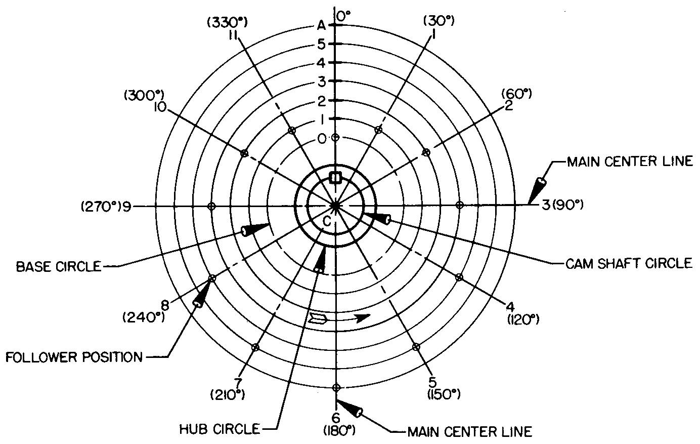
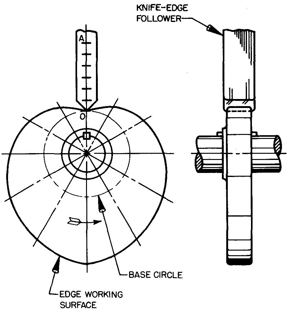
fig. 18-10. Assembly drawing of a radial plate cam
1. Draw the main center lines to intersect at point C. The designer will specify the sizes of the camshaft diameter, the key, the hub diameter, and the location of point 0.
The base-circle radius will always be equal to distance CO. Point 0 on the base circle represents the starting point of the knife-edge follower on the cam edge. This is its closest position to the camshaft. The diameter of the base circle and the maximum rise of the follower govern the size of the cam.
2. Draw radial lines spaced equally every 30°, labeled 1, 2, 3, and so on, clockwise. The number of spacings around the circle should correspond to the number of divisions 0-12 on the displacement diagram (in the case of every 30°, 12 divisions). The angle between the radial lines is called the angle of action.
3. From point 0, lay off the rise 0-A, or 1-1/2 inches, on the vertical center line. The spacings on line 0-A are equal to the spacings 0-A transferred from the displacement diagram.
4. With the compass set at point C and with radii equal to distances C-1, C-2, C-3, and so on, draw light circles.
The arc swung through point 1 will now intersect radial line 1; the arc swung through point 2 will intersect radial line 2; and so on. Since both lobes (halves) of the cam in this example are identical, points in the small circles on radial lines 1 and 11,2 and 10, and so on, are directly across from each other.
At this point it would be well to discuss a fundamental principle which is involved each time a cam is drawn. In actual use, the cam rotates and the follower moves. In this example, the follower will rise and fall 1-1/2 inches for each complete turn of the cam.
On the drawing, however, the cam cannot rotate, but must remain in place. Therefore, we must imagine that the follower is being rotated about the cam on the drawing. The small circles on the radial lines illustrate the different positions of the knife-edge follower as it rotates about the cam.
5. Through the intersections of the arcs thus drawn and the corresponding radial lines (marked with small circles) draw a smooth curve. We now have the cam curve, or edge working surface, as shown in Fig. 18-10.
6. Complete the right-side view. Dimensions for the knife-edge follower and cam plate would normally be supplied to the draftsman by the designer.
The accuracy of the cam curve may be increased by dividing distance 0-12 on the displacement diagram into, for example, twice as many parts. Instead of constructing 12 radial lines (spaced every 30°), we would construct 24 radial lines (spaced every 15°).
The main advantage in having 24 follower positions is in obtaining a more accurate cam curve. In special cases, the draftsman may space the radial lines every 5° or even as close as 1° apart.
Figure 18-10 shows the final cam drawing with the required knife-edge follower.
Example 2. Simple harmonic motion
This is the method a machine draftsman uses to draw a radial plate cam with simple harmonic motion.
Requirements
Assume a roller follower is to rise 2 inches with a simple harmonic motion in 180° and fall 2 inches with the same motion in 180°. The rotation of the cam is counterclockwise.
Procedure
PART I:
Draw the displacement diagram as shown in Fig. 18-11, and described in steps 1 through 5.
fig. 18-11. Displacement diagram : cam with simple harmonic motion
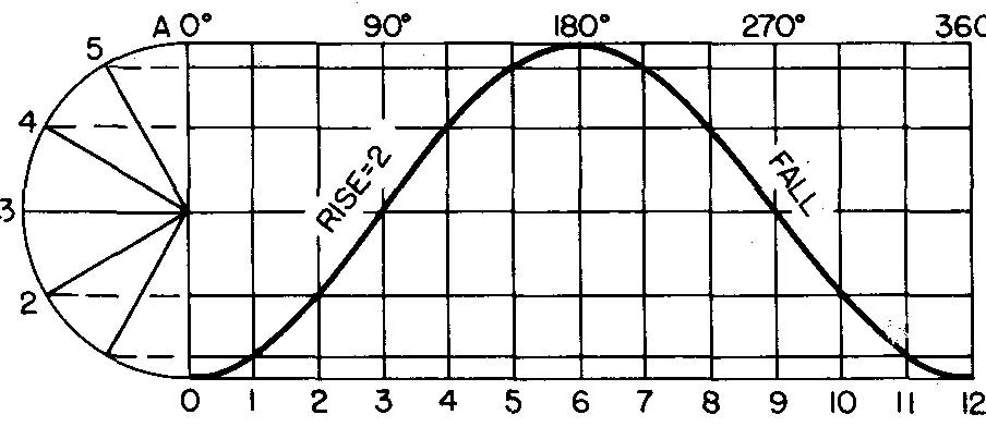
1. Lay off a semicircle with its diameter equal to the maximum rise of the follower, or 2 inches.
2. Lay off the base line 0-12 equal to any convenient distance.
3. Mark the midpoint 6 on line 0-12 and divide both 0-6 and 6-12 into 6 equal divisions. Each division will be equal to 30° cam rotation. Draw vertical lines through these points.
4. Divide the semicircle into the same number of divisions as 0-6 (in this case, 6 divisions) and project points to 0-A. Draw horizontal lines through these points.
5. Using an irregular curve, draw a smooth curve through the intersections of the horizontal and vertical lines (harmonic curve).
PART II:
Draw the views of the radial plate cam, as shown in Figs. 18-12 and 18-13, and as described in steps 1 through 5 and 6 and 7.
fig. 18-12. Layout of a radial plate cam
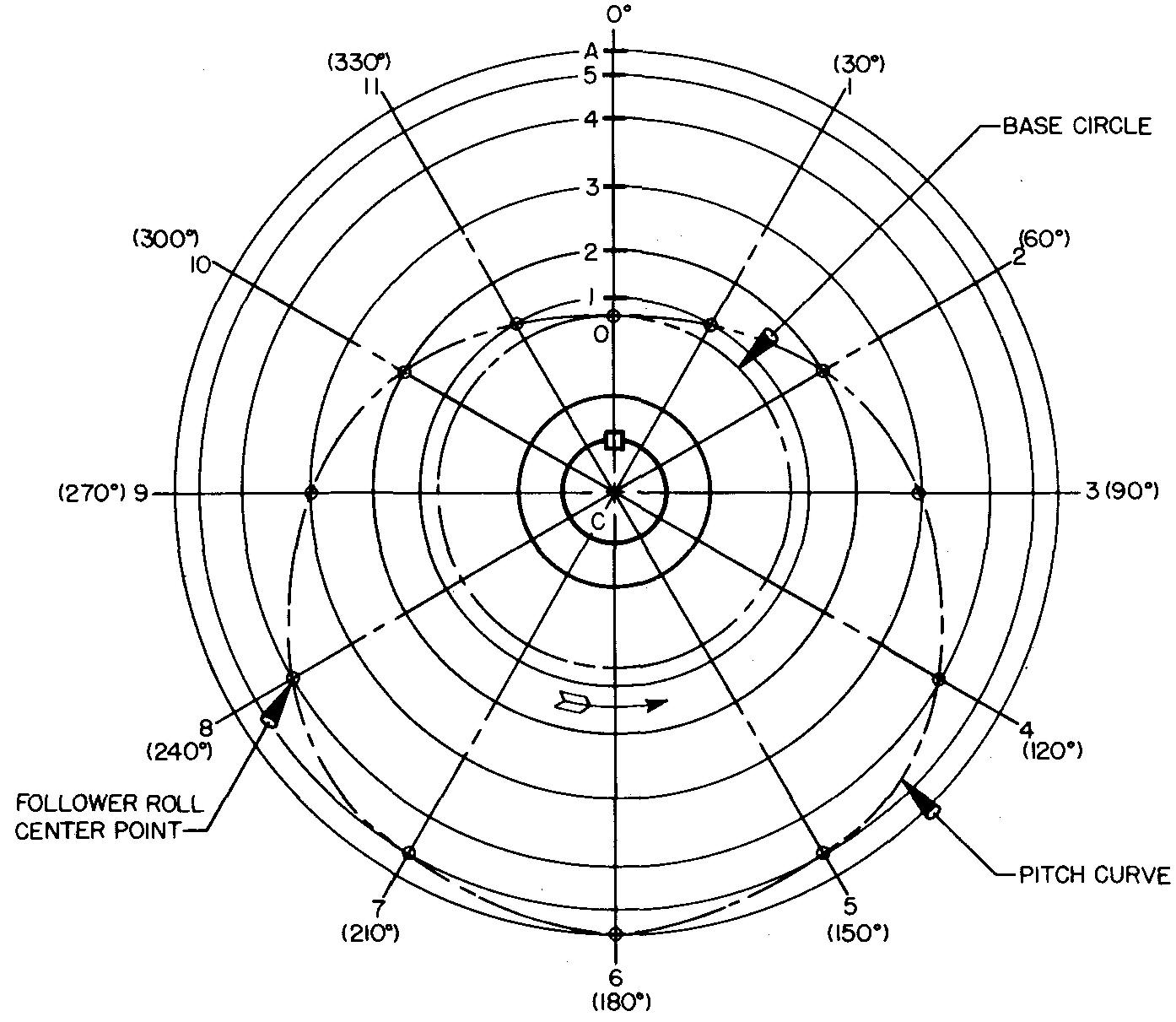
fig. 18-13. Assembly drawing of a radial plate cam
1. Draw the main center lines to intersect at point C. The designer will provide the sizes of the camshaft diameter, the key, the hub diameter, and the location of point 0.
2. Draw radial lines spaced equally every 30°, labeled as 1, 2, 3, and so on. The number of spacings should correspond to the number of divisions 0-12 on the displacement diagram (in this case, 12 divisions).
3. From point 0 lay off the rise 0-A, or 2 inches, on the vertical center line. The spacings on line 0-A are equal to the spacings 0-A transferred from the displacement diagram.
4. With the compass set at point C and with radii equal to distances C-l, C-2, C-3, and so on, draw light circles.
The arc swung through point 1 will intersect radial line 1; the arc swung through point 2 will intersect radial line 2; and so on. The intersecting points are shown as small circles in Fig. 18-12. Since both lobes in this example will be the same, points in the small circles on radial lines 1 and 11,2 and 10, and so on, are directly across from each other.
5. The points thus found are the various positions of the roll center. Connect these points with a smooth curve. This is known as the pitch curve.
6. The edge working surface of the cam may be drawn as follows:
With the compass set equal to the roll radius, swing arcs from the intersection of the pitch curve and radial lines (at each of the small circles).
Draw the edge working surface tangent to the arcs representing the various roll positions, as shown in Fig. 18-13.
7. Draw the right-side view. Dimensions for the roller follower and plate cam are obtained from the designer.
Example 3. constantly accelerated and decelerated motion
This is the method a machine draftsman uses to draw a radial plate cam with constantly accelerated and decelerated motion designed into it.
Requirements
Assume a flat follower is to rise 1-1/2 inches with constantly accelerated and decelerated motion in 180°. It is to fall 1-1/2 inches with the same motion in 180°. The rotation of the cam is clockwise.
Procedure
PART I: Draw the displacement diagram, as shown in Fig. 18-14 (see steps 1 through 5).
fig. 18-14. Displacement diagram : cam with constantly accelerated and decelerated motion
1. Lay off the rise 0-A equal to the maximum rise of the follower, or 1-1/2 inches.
2. Lay off the base line 0-12 equal to any convenient distance.
3. Mark the midpoint 6 on line 0-12 and divide both 0-6 and 6-12 into 6 equal divisions. Each division will be equal to 30° of the cam rotation. Draw vertical lines through these points.
4. Divide the rise 0-A into the same number of divisions as 0-6 (in this case, 6 divisions).
The divisions must be in the proportion of 1, 3, 5, 5, 3, 1.
Draw the straight line B-A to any convenient length.
On line B-A step off 6 divisions spaced in the proportion of 1, 3, 5, 5, 3, 1, or a total of 18 equal spaces.
The first space is one unit; the second space is three units; the third space is five units; and so on. Project each point of the divisions from line B-A to line 0-A.
Draw horizontal lines through these points.
5. Draw a smooth curve through the intersections of the horizontal and vertical lines. This is a parabolic curve, since the curves are arcs of a geometric figure known as a parabola.
PART II: Draw the front view of the radial plate cam, as shown in Fig. 18-15, and as described in steps 1 through 6.
fig. 18-15. Layout of a radial plate cam
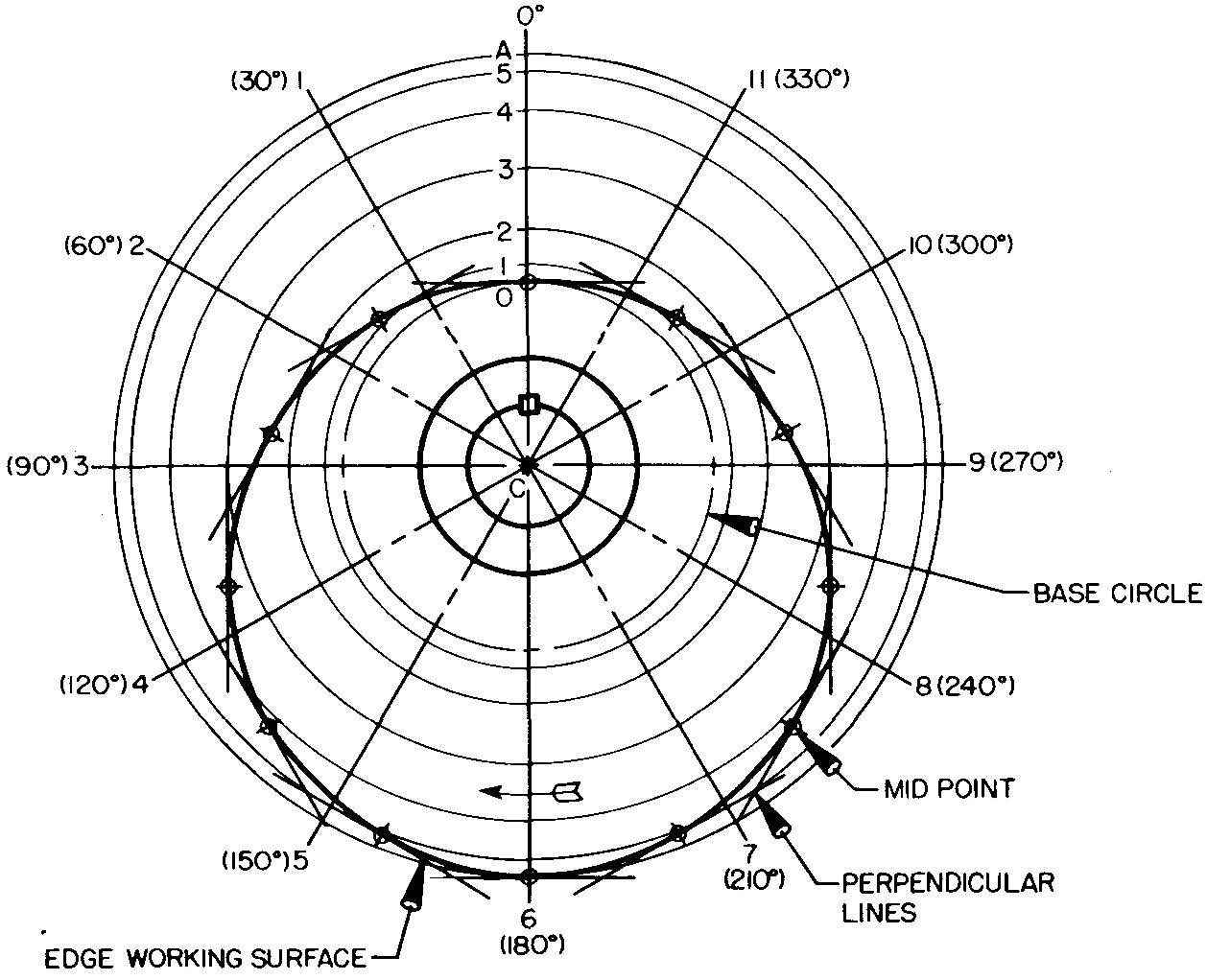
The method of drawing the cam in this example is somewhat different from the method used in drawing the cams in examples 1 and 2.
Unlike the previous two examples, the rotation for this cam is clockwise. As previously discussed, we must imagine that the cam is remaining in place and that the follower is rotating about it.
The exact reverse is true when the cam and follower are installed on the machine, but for drawing purposes we think of the cam as remaining in place.) When the cam rotates clockwise, the radial lines are numbered counterclockwise.
1. Draw the main center lines to intersect at point C. From the design layout, or from information supplied by the design engineer, determine the size of the key, the diameter of the camshaft and of the hub circle, and the location of point 0.
2. Draw radial lines spaced equally every 30°, labeled 1, 2, 3, and so on, counterclockwise. The number of spacings should correspond to the number of divisions 0-12 on the displacement diagram.
3. From point 0 lay off the rise 0-A, or 1-1/2 inches, on the vertical center line. The spacings on line 0-A are made equal to the spacings transferred from the displacement diagram.
4. With the compass set on point C and with radii equal to distances C-l, C-2, C-3, and so on, draw light circles. The arc swung through point 1 will intersect radial line /; the arc swung through point 2 will intersect radial line 2; and so on. Since both lobes in this example will be the same, points on radial lines 1 and 11,2 and 10, and so on, are directly across from each other.
5. Through each point thus found, construct light lines, each perpendicular to the corresponding radial line. Draw each line sufficiently long enough so that one line will intersect, or interlock, with the one next to it, forming a framework of lines.
6. Find the midpoint of each line and mark these points with a small circle, as in Fig. 18-15. A smooth curve may now be drawn tangent to each perpendicular line through each of the small circles.
The curve represents the edge working surface of the cam. The method used constructs an approximate curve, but it is considered to be accurate enough for most drawing purposes.
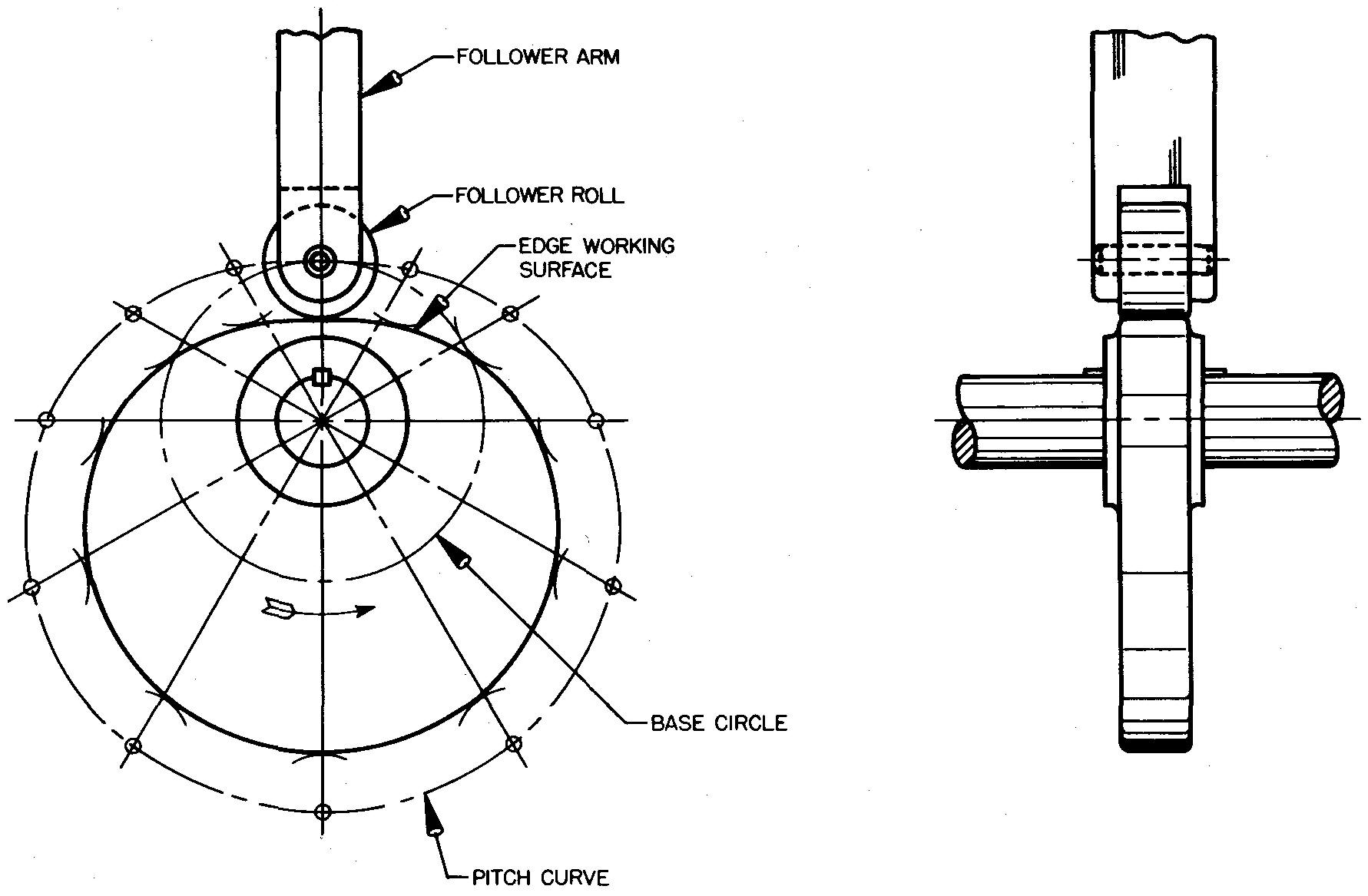
PART III: Complete the front view and draw the right-side view of the radial plate cam, as shown in Fig. 18-16, and as described in steps 1 and 2.
fig. 18-16. Assembly drawing of a radial plate cam
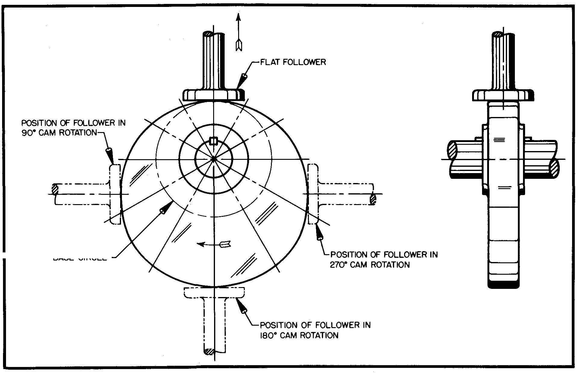
1. From the designer obtain the
dimensions of the flat follower. Draw the follower at the top of the cam.
NOTE: The follower positions at 90°, 180°, and 270° have been shown for
illustration purposes only.
2. Draw the right-side view of the cam and follower.
example 4. radial grooved-plate cam with a combination of motions
This is the method a machine draftsman uses to draw a radial grooved-plate cam with a combination of motions.
requirements
Assume a roller follower is to start with a rise of 2-1/2 inches with constantly accelerated and decelerated motion in 90°; rest to 120°; fall to 1-1/4 inches with simple harmonic motion to 180°; rest to 240°; and fall the remaining distance with modified uniform motion to 0°. The cam rotation is counterclockwise.
NOTE: At a period of rest (also called dwell) the follower remains in place, neither rising nor falling.
procedure
PART I: Draw the displacement diagram, as shown in Fig. 18-17, and as described in step 1.
fig. 18-17. Displacement diagram : grooved-plate cam with combined motions
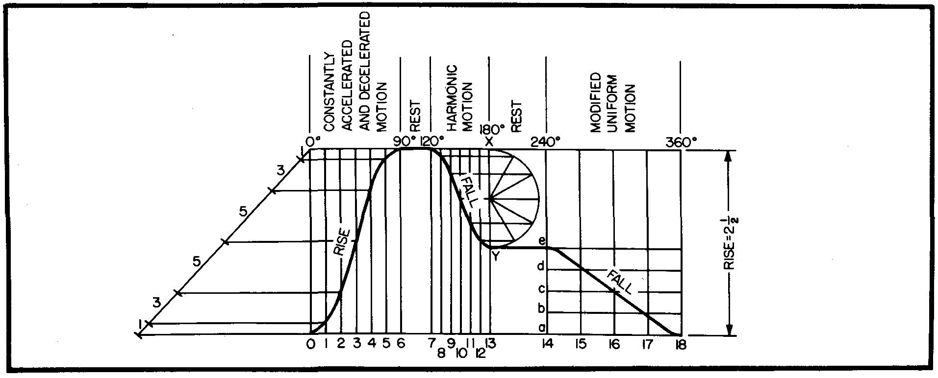
1. Draw the displacement diagram corresponding to the required motions. See PART I of Examples 1,2, and 3.
PART II: Draw the top view of the grooved-plate cam, as shown in Fig. 18-18, and as described in steps 1 through 8.
1. Draw the main center lines, camshaft circle, key, hub circle, and base circle.
2. Draw radial lines 1-6 spaced every 15°, corresponding to the number of divisions on the base line 0-6 on the displacement diagram. Radial line 6 will be at 90°.
3. The divisions 0 through A are obtained from the displacement diagram. Starting at point 0, the follower should begin to rise to a maximum of 2-1/2 inches with constantly accelerated and decelerated motion.
4. With point C as a center, swing an arc from point 1 to intersect radial line 1, point 3 to intersect radial line 2, point 5 to intersect radial line 3, and so on.
5. Since the cam is at a period of rest from 90° to 120°, the follower will neither rise nor fall. Draw radial line 7 at 120°. Continue the arc from the radial line 6 (at 90°) to intersect radial line 7.
6. Starting at 120°, the follower falls a distance of 1-1/4 inches with simple harmonic motion to 180°.
Draw radial lines 8-13 spaced corresponding to the number of divisions on the base line 7-13 on the displacement diagram. Radial line 13 will be at 180°.
At point X on radial line 7, lay off toward the camshaft center the corresponding divisions on X-Y obtained from X-Y on the displacement diagram. Through these points swing arcs with centers at C to intersect with the corresponding radial lines 8, 9, 10, 11, 12, and 13.
7. The cam is at another period of rest from 180° to 240°.
The arc drawn to radial line 13 is continued as before to radial line 14. 8. At 240° the follower falls the remaining distance to the starting position, or point 0, with modified uniform motion.
On radial line 14, in a manner similar to that in step 6, lay off the corresponding divisions e, d, c, b, and a. Swing arcs to intersect radial lines 15, 16, 17, and 18.
NOTE: Point 18 is the same as point 0 on both the displacement diagram and the cam layout.
PART III: Complete the top view and draw the front view, as shown in Fig. 18-19, and as described in steps 1 through 4.
fig. 18-19. Assembly drawing of a grooved-plate cam
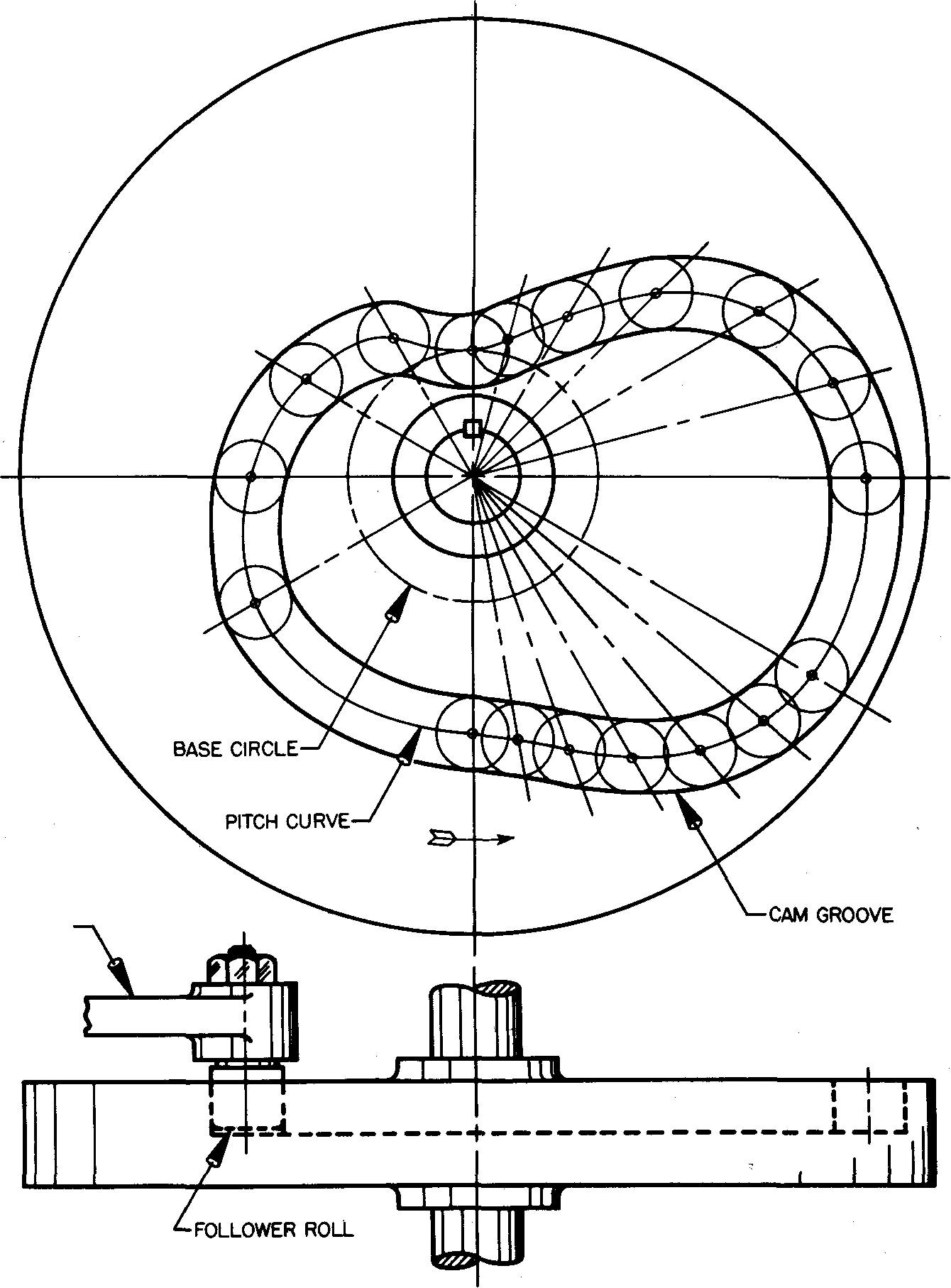
1. Through each point thus found on the radial lines (marked with small circles), draw a smooth curve. This is the pitch curve.
2. Setting the compass equal to the radius of the follower roll, swing light circles with centers at each of the small circles. These are the various roller positions.
3. Two smooth curves may now be drawn tangent to the outer and inner sides of the circles which mark the edges of the follower roller. These curves form the edges of the groove. In actual practice, the width of the groove is made slightly larger than the roller diameter to provide for clearance.
A smooth, easy action is thus obtained. In some cases abrupt changes along the path of the groove may be modified to reduce the possibility of rough action.
4. From the designer, obtain the dimensions of the follower and roll, depth of groove, and so on, and draw the front view.
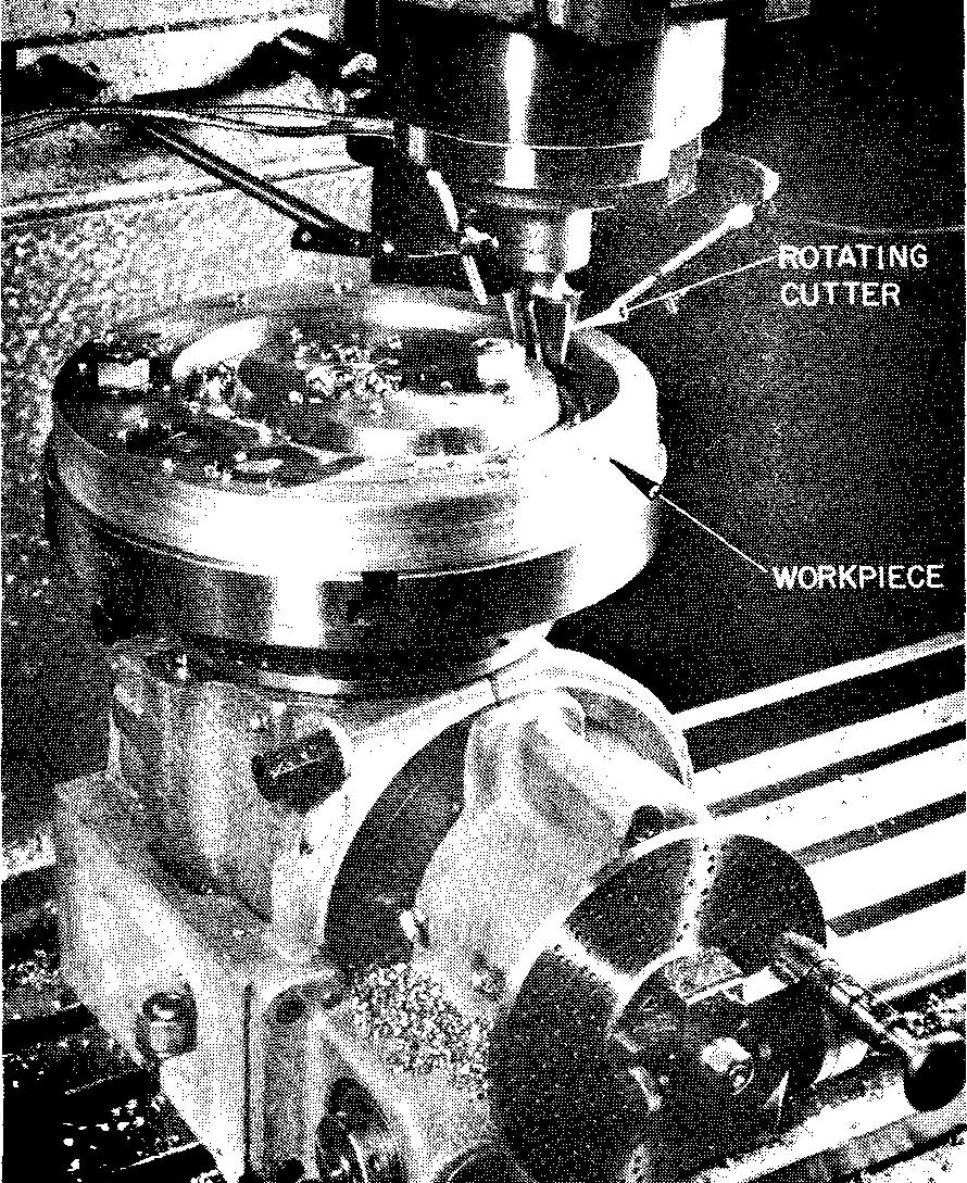
Figure 18-20 shows how the cam groove is machined.
fig. 18-20. machining a grooved-plate cam
example 5. cylindrical-grooved cam with a combination of motions
This is the method a machine draftsman uses to draw a cylindrical-grooved cam with a combination of motions.
Requirements
Assume a cylindrical-grooved cam with a tapered roller follower starts with a maximum outward stroke of 1-7/8 inches in 180° with constantly accelerated and decelerated motion and returns with simple harmonic motion in 180° (or the remaining distance). The cam rotation is clockwise.
NOTE: Depending upon the type
and position of the cam on the machine, the word stroke may be substituted for
rise and fall.
procedure
PART I:
Draw the displacement diagram and the pitch curve as shown in Fig. 18-21, and as described in steps 1 through 7.
fig. 18-21. Layout of a cylindrical cam inches
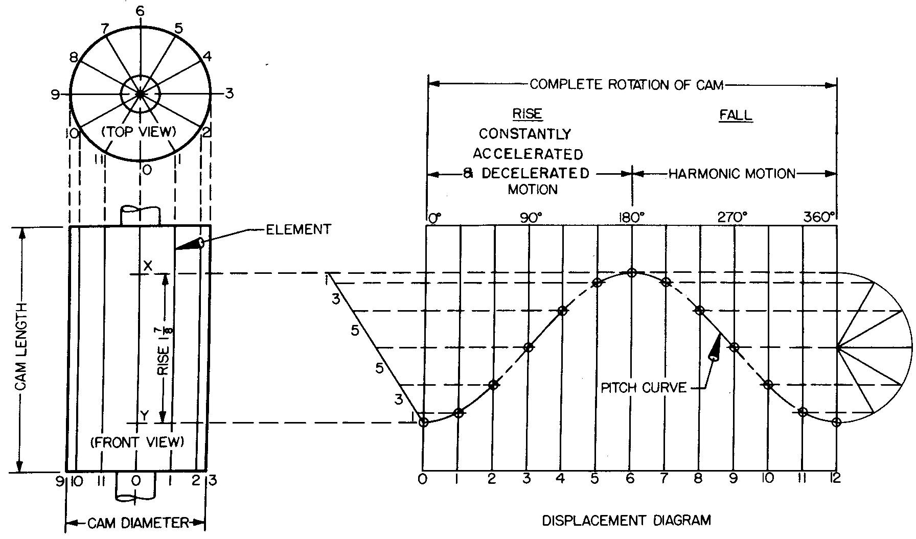
1. Draw the top and front views of the cylindrical cam.
NOTE: In actual practice the dimensions are taken from the design layout.
2. Draw radial lines (spaced every 30° in this example) on the top view. Project points to the front view and draw the elements.
3. Draw the displacement diagram of the cam in the position shown in Fig. 18-21, with 0-12 equal to the circumference of the cam. The distance 0-12 may be drawn by using the spacings taken from the top view. Distance 0-12 may be more accurately worked out by using the formula C = ttD. Distance C (or 0-12) is then divided into 12 equal divisions.
NOTE: For a cylindrical cam, the displacement diagram is also called a development because it represents the complete surface of the cam, which we imagine to be flattened out or stretched out on a flat plane.
4. Distance X-Y equals the rise (1-7/8) in the front view. On the displacement diagram, divide the rise X-Y into spaces proportional to 1, 3, 5, 5, 3, 1.
5. Project points to corresponding divisions on the displacement diagram 0-6. Mark points with small circles. Draw a light, smooth curve through the plotted points of intersection. This is the construction for one half of the pitch curve for constantly accelerated and decelerated motion.
6. The other half of the pitch curve is found by first constructing a semicircle on the displacement diagram with the diameter equal to the maximum rise of the follower (1-7/8 inches).
7. Divide the semicircle into the same number of equal spaces as 6-12 (in this case 6 divisions) and project the points to the corresponding divisions. Mark the points with small circles. Draw a light smooth curve through the plotted points of intersection, completing the entire pitch curve.
PART II:
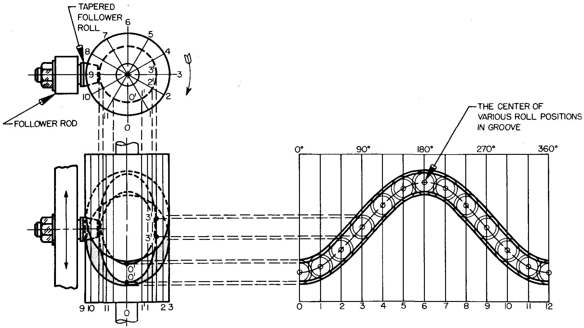
Complete the views as shown in Fig. 18-22, and as described in steps 1 through 5.
1. The diameter of the circle representing the depth of the groove is determined from the design layout. The depth of groove is drawn as a hidden circle in the top view.
2. The sides of the groove are tapered. Again referring to the design layout, we determine the width at the top and bottom of the groove. On the development, set the compass at the center of each of the small circles on the pitch curve. Swing two circles from each point, representing the widths at the top and bottom of the groove.
3. To show the widest part of the groove in the front view, we first project the top and bottom of each large circle. Lines projected from the circle on line 0 are marked off on element 0, lines projected from the circle on line 1 are marked off on element 1; and so on. Two smooth curves are then drawn through these points, representing the edges of the cam groove. The front half of the curve is visible (on elements 9 through 3). The rear half is hidden.
4. To show the bottom part of the groove in the front view, we project the top and bottom of each small circle. Lines projected from the circle on line 0 are marked off on element 0' projected from the top view. Lines projected from the circle on line 1 are marked off on element V, projected from the top view, and so on. The visibility of points on the curve representing the bottom part of the groove must be closely examined. Through the points thus plotted, draw two smooth curves.
5. Complete the front and top views by drawing the tapered roller follower and rod as shown in Fig. 18-22.
fig. 18-22. Layout of a cylindrical cam
example 6. toe and wiper cam
This is the method a machine draftsman uses to draw a toe and wiper cam.
Requirements
Assume a toe and wiper cam is to rise and fall 1-1/4 inches with constantly accelerated and decelerated motion. The angle of action (shown in Fig. 18-23) is 60°. The cam rotation is counterclockwise.
fig. 18-23. Layout of a toe and wiper cam
Procedure
Draw the cam as shown in Fig. 18-23, and as described in steps 1 through 9.
1. Starting with the front view, draw the main center lines, camshaft, key and hub circle, and cam circle.
NOTE: If the material is cast iron, the hub radius should be equal to twice the camshaft radius.
2. Draw the follower to the required dimensions and lay off distance A-D, which represents the maximum rise of the follower (1-1/4 inches).
3. From point A, lay off divisions in the proportion of 1, 3, 5. Project the divisions to center line X-Y, establishing the points B and C.
4. Lay off the angle of action (60°) as shown and divide the angle into three equal radial divisions of 20° each.
5. With point 0 as center, swing arcs through points B, C, and D. Point B will intersect radial line L, point C will intersect radial line M, and point D will intersect radial line K.
6. At the intersection of each arc and corresponding radial line, construct a line tangent to the arc which will be at right angles (90°) to the corresponding radial line.
7. Draw the cam curve, tangent to the extended lines at B', C, and D'. (A more accurate cam curve may be obtained by assuming more divisions in Step 3, as 1, 3, 5, 7.)
8. The cam curve should extend past point D' a small arbitrary distance. It must be understood that the cam will rotate only enough to raise the follower 1-1/4 inches. It must then return to the position shown in Fig. 18-23. A cam such as this has an oscillating motion. It does not rotate through a complete revolution. The follower is shown in phantom at its maximum rise.
9. Draw the right-side view of the cam and the follower.
Review questions (The answers are not given)
1. A cam mechanically converts rotary or cylindrical motion to what type of motion?
2. What is the purpose of a cam?
3. Why is it not possible to purchase a ready-made cam to fit a particular set of requirements?
4. Briefly describe how the cam and follower systems shown in Fig. 18-2A through D work.
5. Briefly describe the purpose of a cam displacement diagram.
6. What does the length of a displacement diagram represent?
7. What does the height represent?
8. Define the term rise.
9. What is done to the curve in uniform motion to smooth out the shock which occurs at the start and stop positions?
10. What type of cam motion is used when a smooth start and stop are desired?
11. In constantly accelerated and decelerated motion what is the relationship of one half of the curve to the other?
12. Define a tangent line.
13. Define a radial line.
14. What two factors govern the size of the cam?
15. A circle divided into 12 equal parts results in spacings of how many degrees?
16. What is the difference between a circle and an arc?
17. Define the angle of action.
18. What is another word which may be used to describe the lobes of a cam?
19. How may the accuracy of the cam curve on the drawing be increased?
20. Is the pitch curve the same as the cam edge? Explain.
21. What word may be
substituted for rise?
Problems
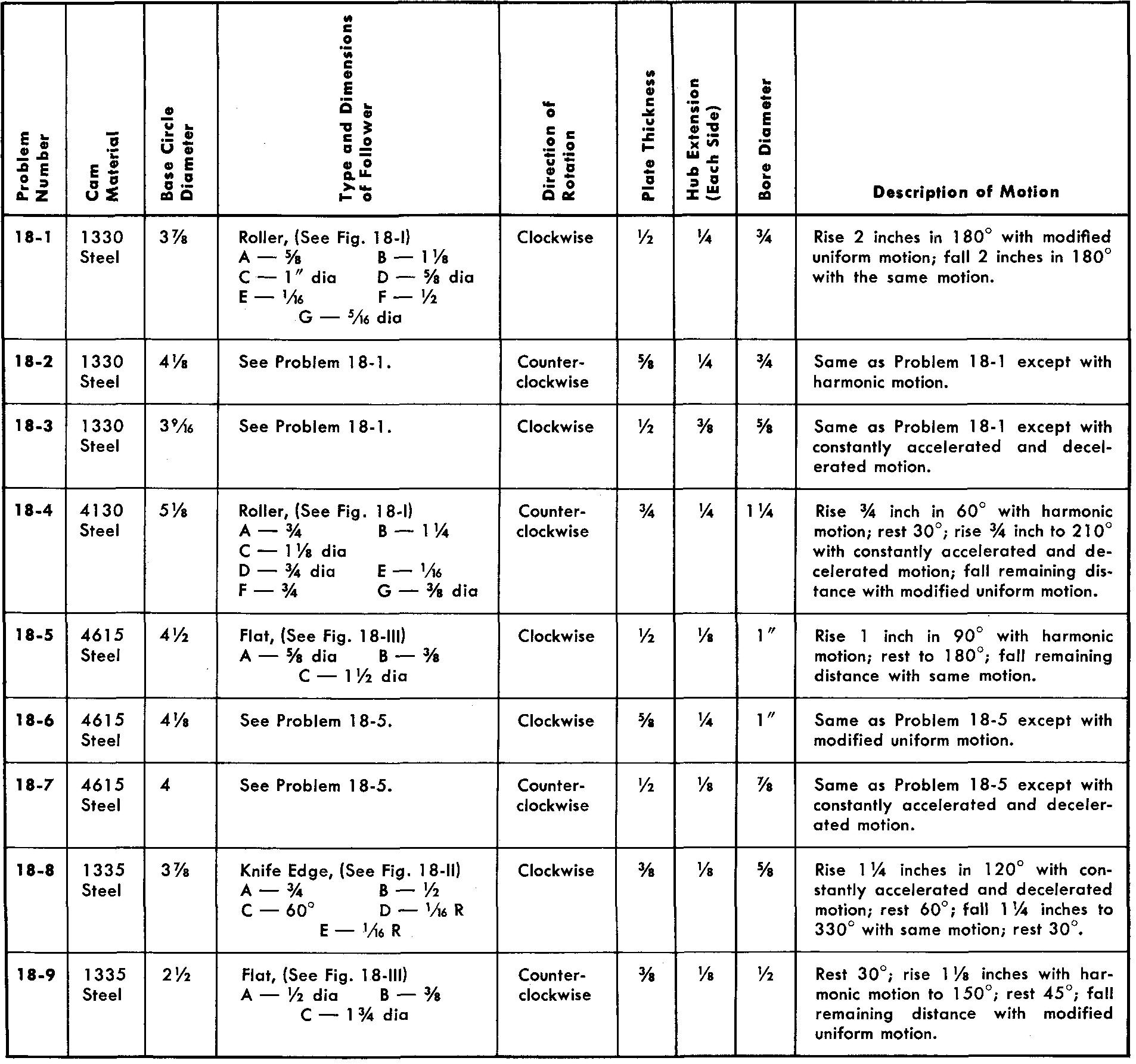
problems 18-1 through 18-9
Radial plate cams
Using one sheet for each problem, draw the displacement diagram and the views of the following radial plate cams and followers. Refer to Figs. 18-10, 18-13, and 18-16.
Views should contain all dimensions and notes necessary for the manufacture of the cam.
Omit dimensions for the follower.
The hub diameter is equal to twice the bore diameter.
Use either a Square or a Pratt and Whitney key.
All bore tolerances are -0.0000, +0.0005.
All cams are to be heat-treated by flame hardening and quenching.
|
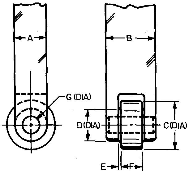
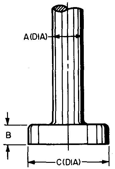
Figure 18-I ROLLER FOLLOWER |
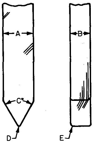
Figure 18-II KNIFE-EDGE FOLLOWER |
 |
 |
|
Figure 18-III FLAT FOLLOWER |
|
 |
Radial plate cams
problems 18-10 through 18-15
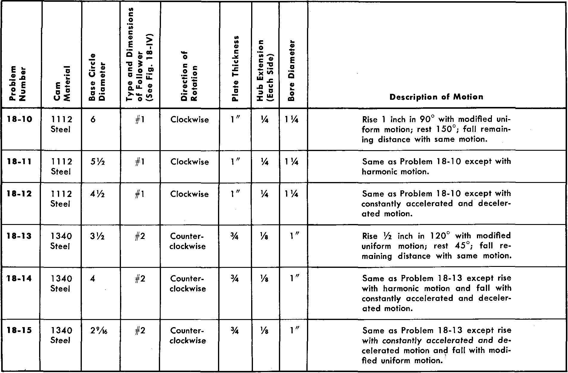
radial grooved-plate cams
Using one sheet for each problem, draw the displacement diagram and the views of the following radial grooved-plate cams and followers. Refer to Fig. 18-19.
Views should contain all dimensions and notes necessary for the manufacture of the cam. Omit dimensions for the follower.
The hub diameter is equal to twice the bore diameter.
Use either a Square or a Pratt and Whitney key.
All bore tolerances are -0.0000, +0.0005.
The depth of the groove is equal to one half the cam plate thickness.
All cams are' to be heat-treated by flame hardening and quenching.
Figure 18-IV
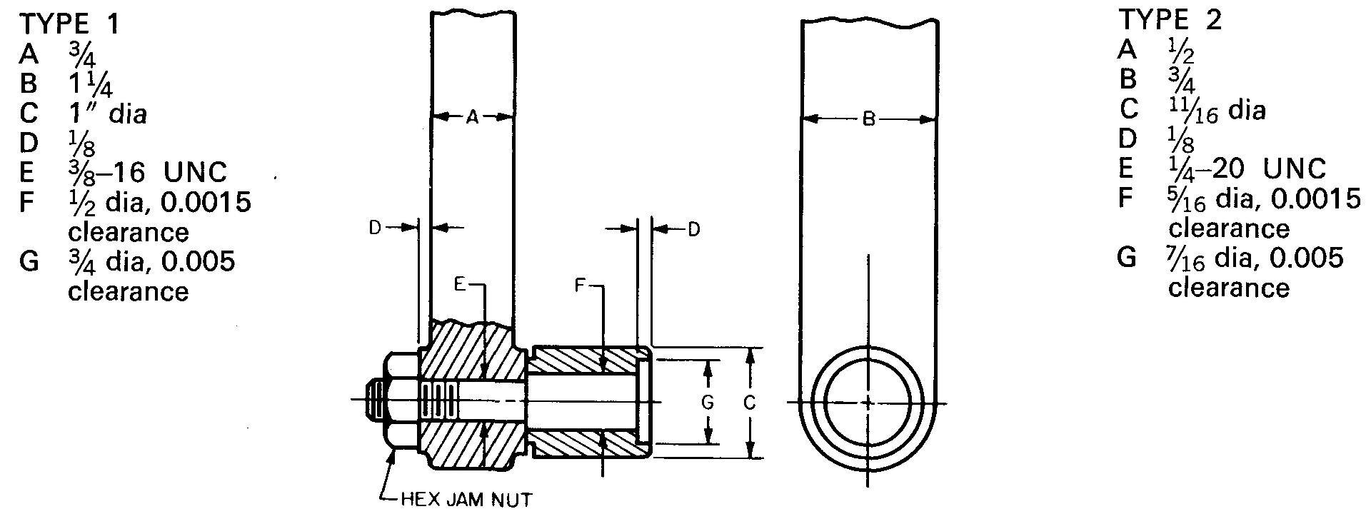
radial grooved-plate cams
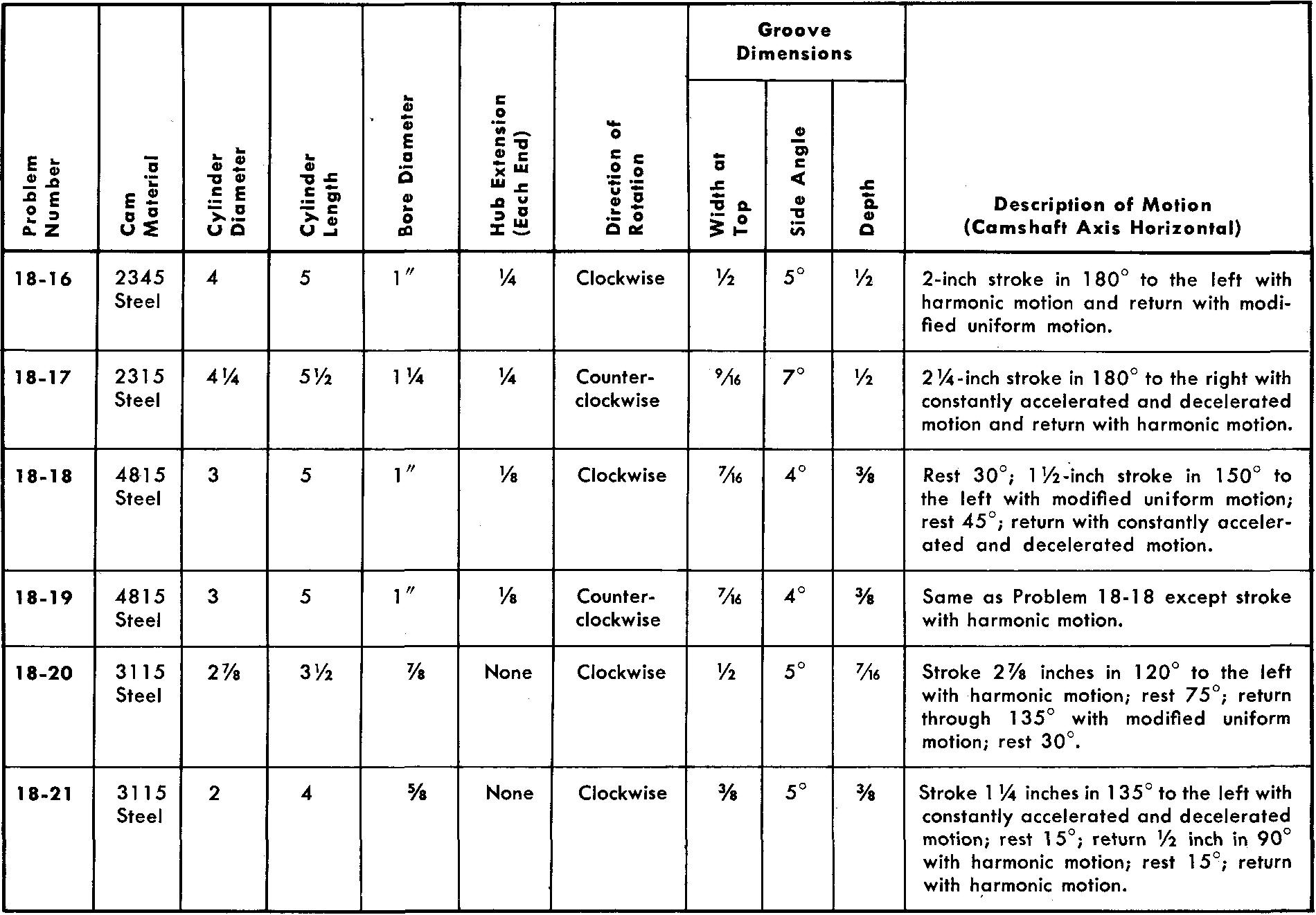
problems 18-16 through 18-21
cylindrical cams
Using one sheet for each problem, draw the development or displacement diagram and the views of the following cams. Assume dimensions for the follower rod and roller. Refer to Fig. 18-22.
Views should contain all dimensions and notes necessary for the manufacture of the cam.
Omit dimensions for the follower.
The hub diameter is equal to twice the bore diameter.
Use either a Square or a Pratt and Whitney key.
All bore tolerances are +0.0003.
All cams are to be heat-treated by flame hardening and quenching.
cylindrical cams
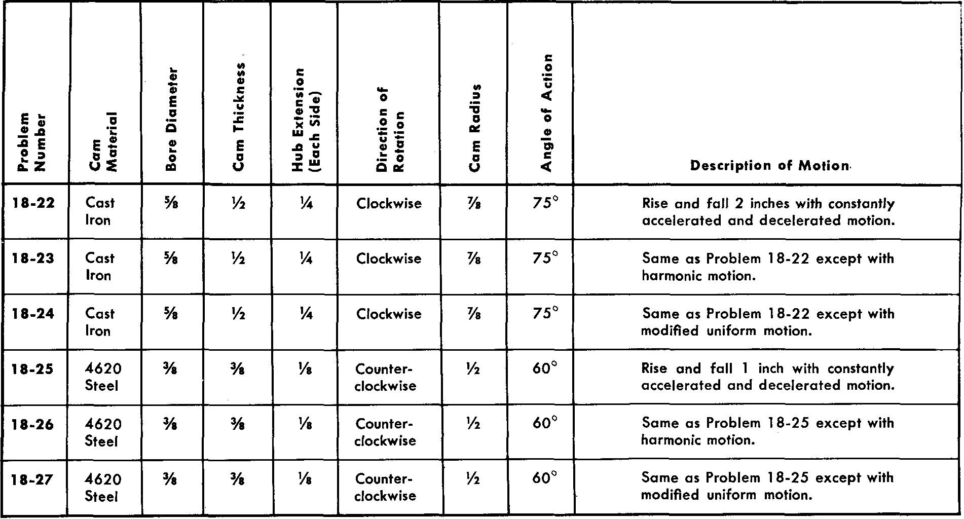
problems 18-22 through 18-27
toe and wiper cams
Prepare two-view detail drawings of each of the following toe and wiper cams. Refer to Fig. 18-23.
Assume dimensions for a follower and draw in proper position using phantom lines.
Use either a Square or a Pratt and Whitne. key.
the hub diameter is equal to twice the bore diameter.
All bore tolerances are -0.0000, +0.0003
All cams are to be heat-treated by flame hardening and quenching.
toe and wiper cams
![]()