Digital sine wave generator
555, 74HC191, 74HC4028, 7476, 7400
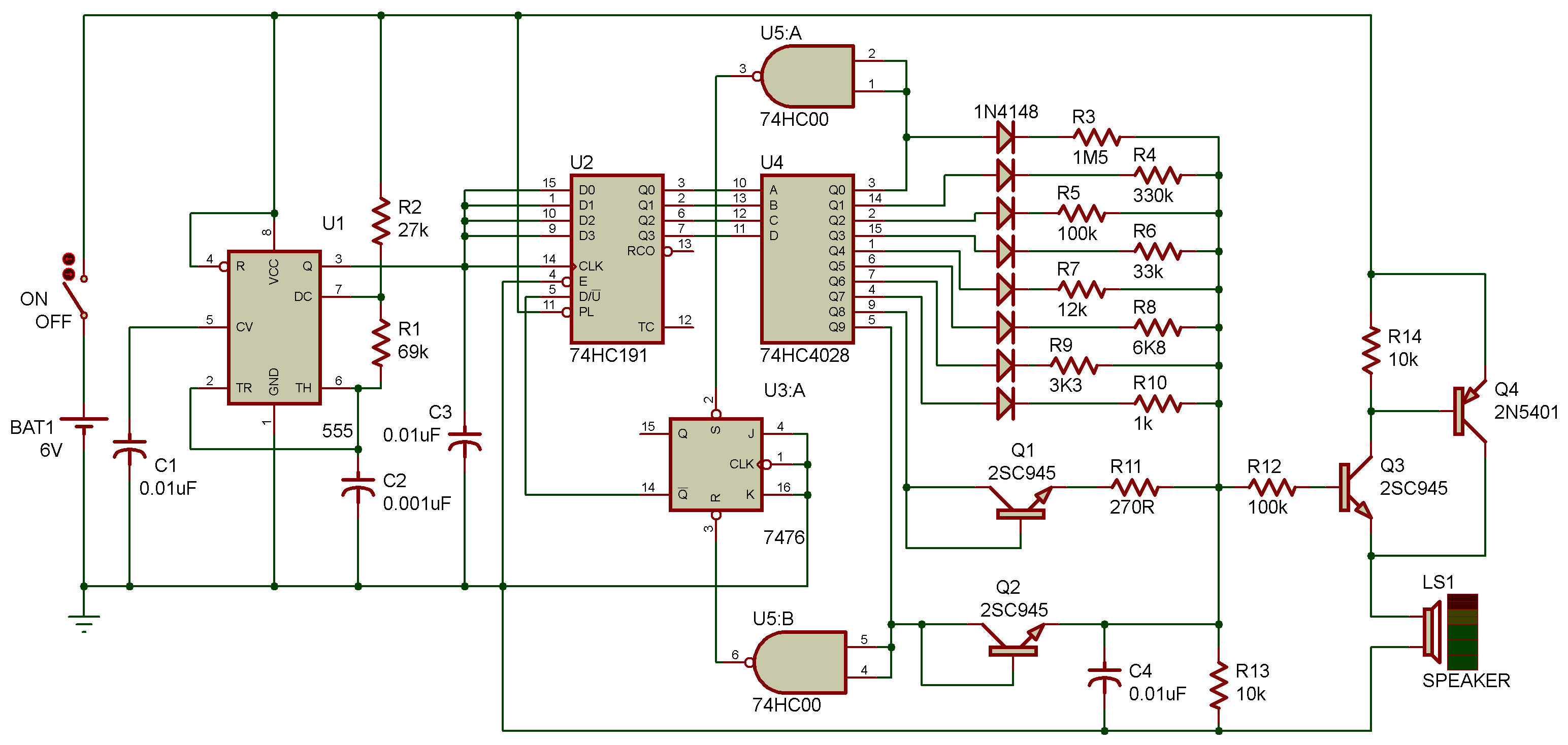
In this project, you're going to make a sine wave using digital technology. Take a look at the schematic. The circuit consists of an oscillator, counter, decoder, and a resistor network. The resistance values in the resistor network are different from one another. Given these hints, try to guess how you can generate a sine wave digitally.
Anyway, finish wiring and turn power ON. You'll hear a monotone from the speaker.
U1 555 is an oscillator, and the counter U2 counts up with the pulses from U1.
The outputs QA - QC of the counter U2 are decoded by the decoder U4.
As the counter U2 counts up, the output Q9 of the decoder U4 changes to H, when the RS flip-flop U3 is reset to switch the counter U2 to count-down mode.
The count-down proceeds until the output Q0 of the decoder U4 goes H, when U3 is set and U2 switches back to count-up. In this way, the counter shifts back and forth in the range of values 0 - 9.
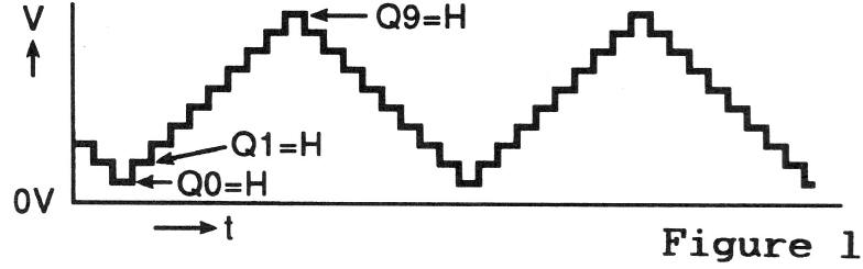
In the meantime, the outputs Q0 - Q9 of the decoder U4 change to H one after another. Therefore, the voltage divided by the resistors connected to Q0 -Q9 and by R13 come to have 10 different voltage values as shown in Figure 1, so that the oscillating tone of this waveform is emitted from the speaker.
| Bill Of Materials For Digital sine wave generator | ||||||
| 14 Resistors | ||||||
| Quantity: | References | Value | ||||
| 1 | R1 | 69k | ||||
| 1 | R2 | 27k | ||||
| 1 | R3 | 1M5 | ||||
| 1 | R4 | 330k | ||||
| 2 | R5, R12 | 100k | ||||
| 1 | R6 | 33k | ||||
| 1 | R7 | 12k | ||||
| 1 | R8 | 6K8 | ||||
| 1 | R9 | 3K3 | ||||
| 1 | R10 | 1k | ||||
| 1 | R11 | 270R | ||||
| 2 | R13, R14 | 10k | ||||
| 4 Capacitors | ||||||
| Quantity: | References | Value | ||||
| 3 | C1, C3, C4 | 0.01uF | ||||
| 1 | C2 | 0.001uF | ||||
| 5 Integrated Circuits | ||||||
| Quantity: | References | Value | ||||
| 1 | U1 | 555 | ||||
| 1 | U2 | 74HC191 | ||||
| 1 | U3 | 7476 | ||||
| 1 | U4 | 74HC4028 | ||||
| 1 | U5 | 74HC00 | ||||
| 4 Transistors | ||||||
| Quantity: | References | Value | ||||
| 3 | Q1-Q3 | 2SC945 | ||||
| 1 | Q4 | 2N5401 | ||||
| 8 Diodes | ||||||
| Quantity: | References | Value | ||||
| 8 | D1-D8 | 1N4148 | ||||
| 3 Miscellaneous | ||||||
| Quantity: | References | Value | ||||
| 1 | BAT1 | 6V | ||||
| 1 | LS1 | SPEAKER | ||||
| 1 | ON | OFF | ||||

![]()