
The big ear
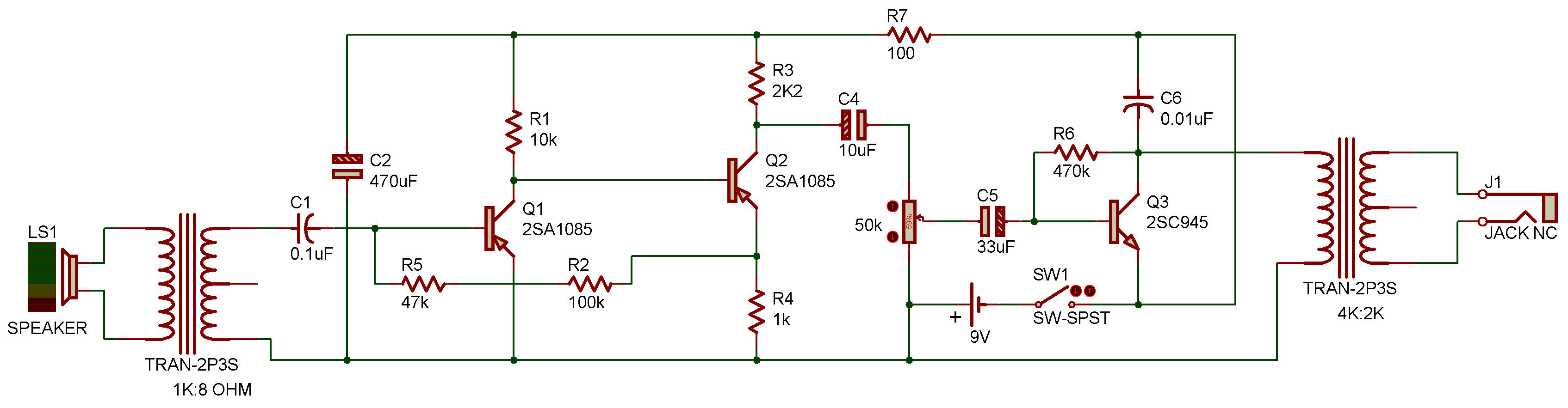
Trans out = 1K : 8Ω
; Trans IN = 4K : 2K
This project is a high-gain, three-stage audio-amplifier that allows you to increase sound levels just like a high-gain hearing aid see the Amplifiers section.
You can use this circuit with extension leads on the Speaker (used as a microphone) up to about 30 feet (9 m) or so. With this setup it is possible to "bug" an area and hear the slightest whisper. When you use the Speaker in this experiment, you must place the Earphone in your ear or the amplifier will oscillate due to acoustic feedback.
Start operation with the Volume Control initially set at minimum and then increase the setting for required volume. This procedure must be used because the gain is so high that the open circuit layout causes an ultrasonic oscillation to occur at very high Control settings. When this oscillation occurs the volume drops significantly.
We're using the Speaker as a dynamic microphone with the voltage stepped up with the Transformer to a higher level for the first amplifier. The first two Transistors are connected into a high-gain "ring-of-two" circuit. The volume Control is placed at the output of the ring-of-two amplifier. This position is better than at the input because it provides a better signal-to-noise ratio.
Any amplifier stage that precedes the volume Control is placed at the output of the ring-of-two amplifier. Any amplifier stage that precedes the volume Control and is designed for high-gain, low-noise operation is called a "pre-amplifier".
The volume Control has no DC current flowing through it. This is also a desirable design consideration as DC current in a control eventually causes the Control to become very noisy and erratic.
The 2SC output stage is a common-emitter amplifier with fixed base current bias and a 0.01 uF high frequency bypass across the C-E output. This Capacitor cures the above mentioned ultrasonic oscillation on most hook-ups, but if your circuit should happen to be a little out of tolerance, be aware of this problem and recognize it for what it is.
The 100 ohm Resistor and 470uF Capacitor form what is called a decoupling filter. This is required in multiple-stage amplifiers such as this to keep oscillations from occurring due to Battery resistance. If batteries were perfect constant-voltage sources this decoupling would not be necessary, but as you will learn, there is no such thing as a "perfect" or "ideal" practical component.
If you have a VOM, this is a good circuit for measuring and recording voltages. By the way, if you don't understand all the technical explanations in this project, don't worry, we don't expect you to get everything at first.
As the projects go by, we will gradually explain and define the new terms for you, and by the time you finish all the projects you'll understand everything (we hope).
![]()