Emitter follower
In this project, you're going to build an emitter-follower circuit and learn its workings from the brightness of an LED.
Emitter-followers are commonly used circuits, which are current amplifiers. They do not amplify voltage (the voltage gain is unity). Just imagine—if you connected LED 1 directly to the control volume without using the transistor Q1, you wouldn't have the enough current to illuminate LED 1.
So, the emitter-follower shows its stuff. You place the emitter-follower between the control volume and LED 1, and you have adequate current flowing to LED 1.
When you finish wiring, turn power ON and try to rotate the control volume clockwise. LED 1 turns brighter and brighter accordingly, showing it's conducting sufficient current.
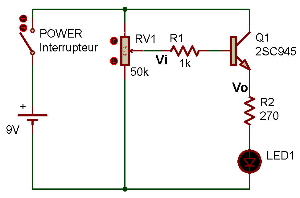
Look at the schematic and fix its form into the memory. Note that the collector of Q1 is directly connected to the power supply without going through a resistor. The emitter is connected to a resistor. This is the basic form.
This circuit is often called a buffer. Simply speaking, when viewed from the control volume, little load current flows, so the control-side circuit is not influenced by the load-side circuit. From a viewpoint of the load side, it can receive a supply voltage of the value (mid-point voltage of control volume, Vi) - (Vbe), from the emitter of Q1.

![]()