
RF Signal Meter
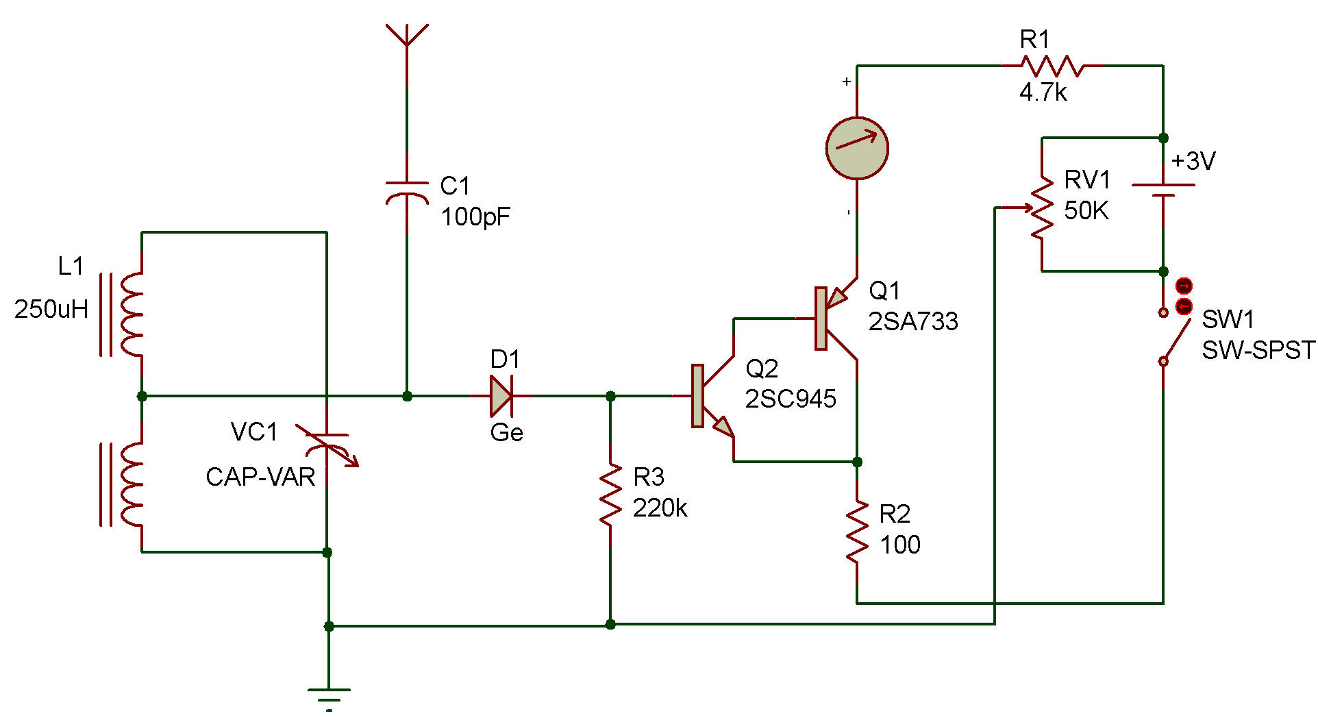
The purpose of this project is to measure the intensity of RF signals. The circuit is very much like a radio circuit you have already built (see Radio Section), except that the output is connected to the Meter instead of the Speaker or Earphone.
Operation is as follows:
1) Complete all wiring except for the Antenna and Ground connection.
2) Adjust the Control so that the Meter is just beginning to move. Make this adjustment carefully, too much current could damage the Meter.
3) Connect the Antenna and Ground and adjust the Tuning Capacitor until you get a reading on the Meter.
Note: It may take a strong radio station to cause more the a slight change in the Meter reading.
This circuit works by amplifying the modulated DC signal which is created when the RF signal is "detected" by the Diode. This signal causes changes in the base current supplied to the 2SC Transistor (which we have set to a 'threshold' level by adjusting the Control in step 2).
The 2SC Transistor (C-E circuit) supplies base current to the 2SA Transistor, and its C-E circuit controls the Meter. By connecting the Earphone you can listen to the RF signals you are measuring.
CAUTION: To avoid damage to the Meter, set the Control to 0 before making the wiring connections.
![]()