
Meter Amplifier
You will see the combination of a DC amplifier and the Meter, in this project. This combination of the Meter with a DC amplifier is frequently used to improve the Meter sensitivity, and it is also required to prevent other circuits from being affected by the low resistance of the Meter, when it is connected solely to the other circuits.
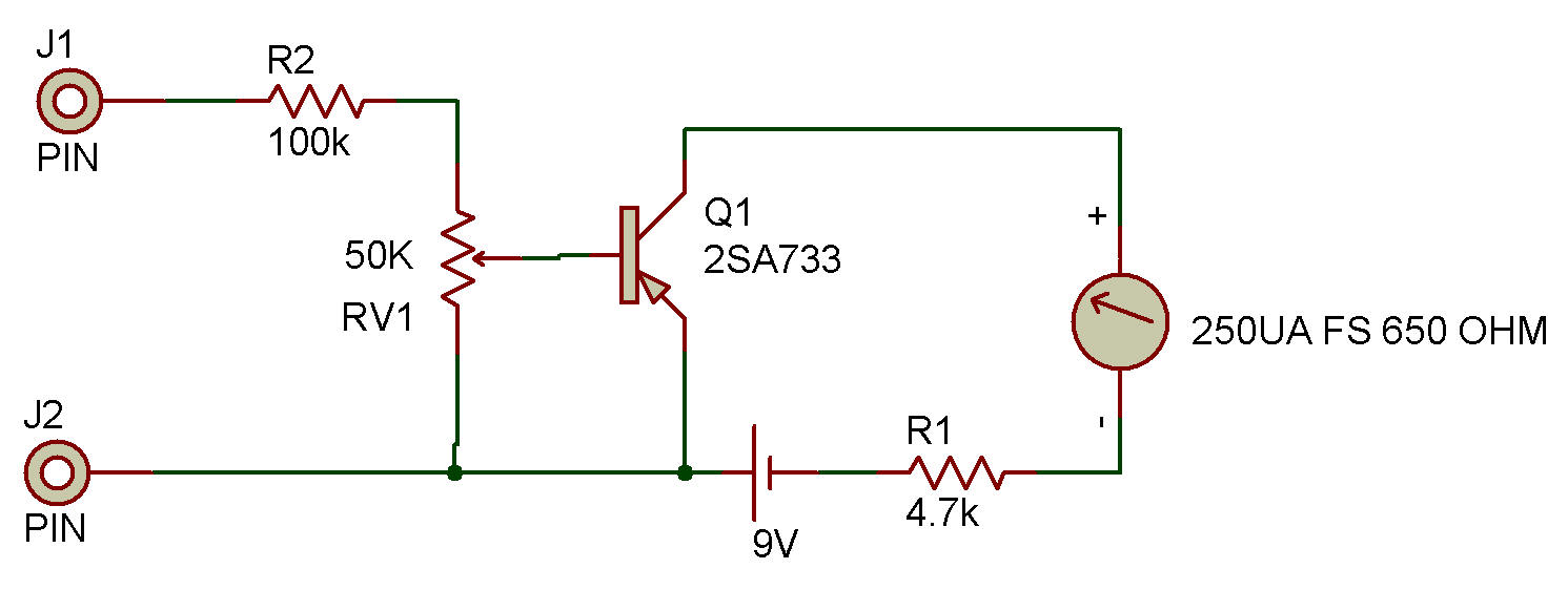
The DC amplifier we use in our test is one of the simplest type, but it makes us remember a fact that can be overlooked. Set the Control knob to the "0" position, and connect the Probes to the 3V Battery (observe correct polarities).
Then slowly turn the Control knob clockwise. How does the Meter pointer move?
It almost stays still until the Control knob reaches "5" (approx.). The Meter pointer starts to swing when the Control knob is turned beyond that point. Change the Probe connections to a 1.5V battery. At this moment the Meter pointer stays still no matter where the Control knob is positioned, or maybe it moves a bit when the Control knob is turned fully clockwise.
No current is allowed to flow into the B-E junction of the Transistor unless certain bias voltage (about 0.6V for a silicon Transistor) is applied. In our test the Meter does not respond against any voltage lower than about 1.8V, as the base circuit of Transistor has both the 100K and 50K Control resistance. The project Transistorized DC Voltmeter in Testers Section, show a way to solve this problem.
![]()