
Voice Controlled Switch
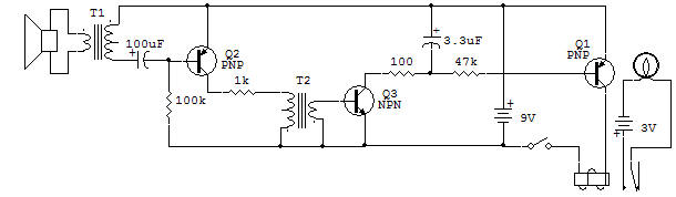
T1:
Output (900 CT : 8 ohm) - T2 : Input (4K CT : 2K)
This project demonstrates how your voice can be used to turn on a transmitter or tape recorder automatically. The speaker is used as a dynamic microphone and all three Transistors are used to change the audio signal to a DC voltage high enough to energize the Relay.
Project VOX — Voice Operated (Transmit) Relay in Switches scetion is a similar type of circuit, but it uses the IC to provide most of its amplification.
The VOX (voice operated transmit) circuit is used by radio amateurs on transmitters as a way of obtaining the convenience of a telephone. The Relay in this project only turns on a Lamp, but when used with transmitters it is wired to replace the function of the SEND/RECEIVE switch.
This circuit has the following features:
The 2SA(Q2) is used as a class A amplifier see in Amplifier Section with Transformer-coupling in the output. Fixed base-bias current is supplied from the 100K base Resistor.
A 1K collector Resistor is used to both limit the maximum current to the 2SA(Q2) and to prevent unwanted (parasitic) oscillations in this stage.
The 2SC(Q3) is operated without any base-bias voltage or current so this stage is operating class C. One desired feature of this class of operation is that the signal is effectively rectified as well as amplified. The output of this stage does not have to be rectified by a Diode.
The 100 ohm Resistor functions to limit peak collector current for the 2SC Transistor.
The 3.3uF Capacitor filters the signal so that the 2SA(Q1) receives relatively smooth DC base current. The 2SA(Q1) is the Relay switching Transistor. It also is not biased ON and relies entirely on the presence of a signal that has been converted to DC across the 3.3uF. The ON and OFF delay of this circuit is affected most by the value of the 3.3uF Capacitor.
You may want to experiment with the value of the Capacitor to see the results. To try the 100uF (which is already in the circuit), replace it with the 10uF for the input to the 2SA(Q2).
Turn the Control to obtain an adequate sensitivity. WARNING: Too much sensitivity causes the circuit to malfunction with a click sound when the Relay is turned OFF (acoustic feedback).
![]()