
Lamp Blinker Circuit
This project demonstrates the operation of a lamp blinker circuit like those you have seen blinking on the tops of tall buildings and radio antenna towers.
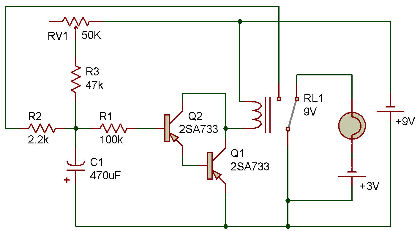
The actual switching of the Lamp current is done with reliable Relay contacts, but the timing and control functions are provided by a switching Transistor.
The rate of flashing is adjustable from about one or two per second, using the 50K Control. This exact circuit could be used as an emergency warning light on your car or bicycle. A flashing red tail light on a bicycle is more easily seen than a steady light.
The Lamp is wired to the normally closed (N. C.) contacts of the Relay, so the Relay must be energized to turn the Lamp OFF. This provides fail-safe operation. That is, if the control circuit doesn't work, the Lamp is ON and will provide some protection even though it won't be flashing.
When the 9V Battery is first connected, the Transistor remains OFF while the Capacitor begins to receive a charge through the 47K Resistor and 50K Control. After a short time the charge is high enough to allow the voltage to turn the Transistor ON. When the Relay is energized through the ON Transistor, it does two things: turns the Lamp OFF, and places the a discharging Resistor across the timing Capacitor.
This discharges the Capacitor to a point where the Transistor loses base-bias and is turned OFF, setting conditions back to the beginning of the cycle. A characteristic of the Relay which helps give a delay in the OFF part of the cycle is that the current required to energize the Relay coil (and move the contacts) is higher than the current required to keep the Relay energized (and hold the contacts in position).
The 2.2K Resistor is also included to delay the OFF time. A secondary advantage of the 2.2K Resistor is that it saves the contacts of the Relay from a destructive surge of current from the Capacitor.
Another Version
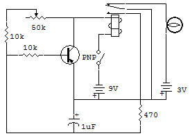
![]()