Resistor in series and in parallel
The purposes of this project are to study basic series and parallel connected Resistors and to consider a shunted (bypassed) DC current meter. Let's" consider the shunted DC current meter first, as it is used to study the effects of series and parallel connected Resistors.
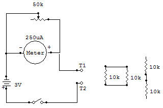
The Meter supplied with this kit requires about 250uA (microamperes) to produce a full-scale needle deflection. The resistance of the fine windings of wire in the Meter coil is about 650 ohms. Now consider this resistance when the Meter is shunted ("paralleled") with the 50K as shown in the Schematic diagram.
1. If the Control is adjusted for zero ohms across the Meter, it would act as a short circuit allowing almost unlimited current to flow before the Meter scale could reach full scale.
2. If the Control is adjusted for 650 ohms (equal to the meter resistance), it would pass the same amount of current as the Meter. A 250uA Meter current and 250uA shunt current would result in a total of 500uA. Pull scale Meter readings at this time then represent a total current flow of 500uA.
3. If the Control is adjusted for its full 50K, it would pass such little current compared with the Meter that total current would be practically equal to that of the Meter alone.
4. From the above it can be seen that with proper adjustment of the 50K Meter shunt (Control), the effective full scale Meter current may be almost any value from 250uA and upward. There is a practical limit though because of the current handling capability of the Control. Therefore the maximum current shouldn't be allowed to exceed about one milliamp through the Control.
Now let's consider series and parallel connected Resistors. It seems logical (and is) that when resistances are connected in series their resistance values add together to obtain the total resistance. Expressed in formula form this is RT=R1 +R2 for the circuit shown. Parallel connected resistors present quite a different result. As with the shunted Meter discussed above, parallel (or shunted) Resistors cause more current to flow and therefore the resistance to current flow to decrease. This may be nicely demonstrated as follows:
1. Connect the circuit for series 10K Resistors. Adjust the 50K for a Meter reading of 2 on the blue meter scale. Do not move this Control setting for the following tests.
2. Now temporarily remove, one 10K Resistor from the circuit and replace it with a wire so that only one 10K is in the circuit. Current is now higher on the blue scale (4 is typical and expected).
3. Parallel the 10K Resistors and measure the current. Current is higher on the blue scale (8 is typical and expected).
Now let's consider the implications of the above tests. Series connecting Resistors increase the resistance and decrease the current. For our test we showed that series connecting equal value Resistors caused the current to be half of what it is with one Resistor (2 is half of 4).
Parallel connecting Resistors causes the resulting resistance to decrease and the current to increase. Our test verified the fact that paralleling equal value resistors causes the current to double (from 4 to 8), and if the current is doubled, the resistance must have decreased to half of the single Resistor value.
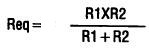
The formula for finding the equivalent resistance Req when two resistors are connected in parallel is:
If you want to check series and parallel connections of other Resistors, be careful not to allow the resultant resistance to go below about 2.2K or the Control may be damaged.

![]()