FM More power
Everyone wants to transmit as far as possible and build the most powerful transmitter in the world. But you have to be careful.
An FM transmitter can reach an enormous distance with just a few milliwatts and when you start building one with a consumption of 1watt or more, you are getting into serious territory.
We produce a 30mW bug called the AMOEBA and it was tested by a hobbyist on top of a mountain and it transmitted 40km (26 miles) to his home.
We regularly get 400m in a built-up area, so you can see, hundreds of people in the 400m radius could be detecting the channel. You can imagine how far a 1watt transmitter will travel and how many people could be involved. But it is not just the wattage.
When you design a powerful transmitter, you must be very careful to eliminate unwanted harmonics. These are frequencies that are generated by the circuit (and get radiated with the signal) to produce all sorts of havoc.
They are at a lower power-level than the main frequency but they are very difficult to detect. A powerful transmitter can produce a lot of these and nearby neighbors can get very upset if your device interferes with their baby monitor or radio reception or home intercoms etc.
Since I live near a training airport, I have to be very careful not to produce anything that might upset the communications between the tower and training aircraft. Airport channels and emergency channels are very close to the frequencies we are using and when a transmitter gets into the 1watt category, you don't know who you may be upsetting.
The circuits we have presented to date are less than 50mW output and very little real interference can be produced.
The next 3 circuits are for experimental purposes and have an output of about 200mW to 400mW.
A circuit diagram does not show the screening necessary to keep the harmonics to a very low level. You need to see a photo of the unit and how the components have been laid out.
The construction and placement of the filtering components on the output is also important. That's why these circuits are more complex than just putting the components together and connecting a supply.
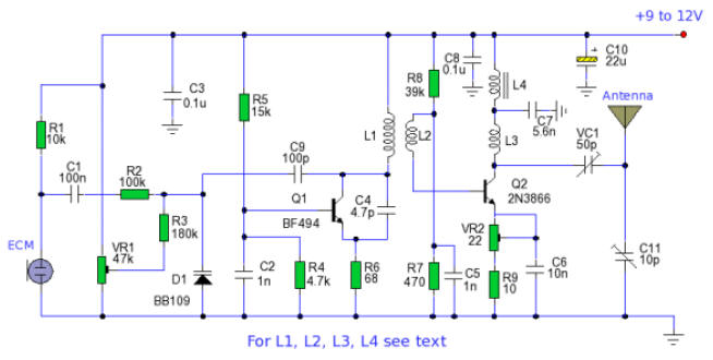
200mW FM TRANSMITTER
The power output of many transmitter circuits are very low because no power amplifier stages are incorporated. The transmitter circuit described here has an extra RF power amplifier stage, after the oscillator stage, to raise the power output to 200-250 milliwatts.
With a good matching 50-ohm ground plane antenna or multi-element Yagi antenna, this transmitter can provide reasonably good signal strength up to a distance of about 2 kilometers.
Circuit Notes
The circuit is built around transistor T1 BF494. It is a low-power variable-frequency VHF oscillator.
A varicap diode is included to change the frequency of the transmitter and to provide frequency modulation of the audio signals.
The output of the oscillator is about 50 milliwatts.
Transistor T2 2N3866 forms a VHF "class A" power amplifier. It boosts the oscillator signal power four to five times. Thus, 200-250 milliwatts of power is provided at the collector of transistor T2.
For best results, construct the circuit on a PC board with all components closely connected and put the transmitter in an aluminum case.
Coil winding details:
L1 - 4 turns of 20 SWG wire close wound on 8mm diameter plastic former.
L2 - 2 turns of 24 SWG wire near top end of L1. (Note: air core for the above coils)
L3 - 7 turns of 24 SWG wire close wound with 4mm diameter air core.
L4 - 7 turns of 24 SWG wire-wound on a ferrite bead (as choke)
Potentiometer
VR1 is used to vary the fundamental frequency whereas potentiometer
VR2 is used as power control.
For hum-free operation, connect the transmitter on a 12V rechargeable battery pack of 10 x 1.2- volt Ni-Cd cells.
Transistor T2 must be mounted on a heat sink.
Do not switch on the transmitter without a matching antenna.
Adjust both trimmers (VC1 and VC2) for maximum transmission power.
Adjust potentiometer VR1 to set the frequency to about 100MHz.
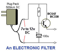
POWERING A BUG
It is always the best to power a bug from a battery. It keeps the whole project simple. However if you want to power a bug for a long period of time, here is a circuit that will reduce the hum from a normal plug pack by a factor of about 2,000.
This means a 20mV ripple will be 1uV and will not be noticed. Any background hum is annoying and very difficult to remove with electrolytics.
This circuit is the answer. The 1k and 100u form a filter that makes the 100u ten times more effective than if placed directly on the supply-line.
The transistor reduces the ripple by a factor equal to the gain of the transistor - about 200.
The result is a reduction by a factor of 2,000.
The circuit is suitable for up to 100mA.
A power transistor can be used, but the 1k will have to be reduced to 220R for 500mA output.
The output of the circuit is about 0.6v less than the output of the plug pack.

![]()