A rectifier circuit by diode bridge LM324
In this project, you are going to learn the function of a diode bridge that rectifies an alternating current voltage and converts it into the direct current voltage, by listening to the a beep sound from the earphone.
Before powering ON the circuit, set the switch S1 to the down position. Put the earphone to your ear and turn the power switch S1 ON. You can hear a beep sound.
Turn the S1 to the up position and it stops the "beep" sound.
When the S1 is in its down position, a signal coming to the earphone is not rectified by the diode bridge; it is an alternate current which makes a "beep" sound.
If you turn the S1 to its up position, a signal coming to the earphone is rectified by the diode bridge and does not make a "beep" sound.
In this experiment, it becomes clear that an alternate current (which makes a "beep" sound in the earphone) is rectified (which does not sound anything in the earphone) by means of a diode bridge circuit.
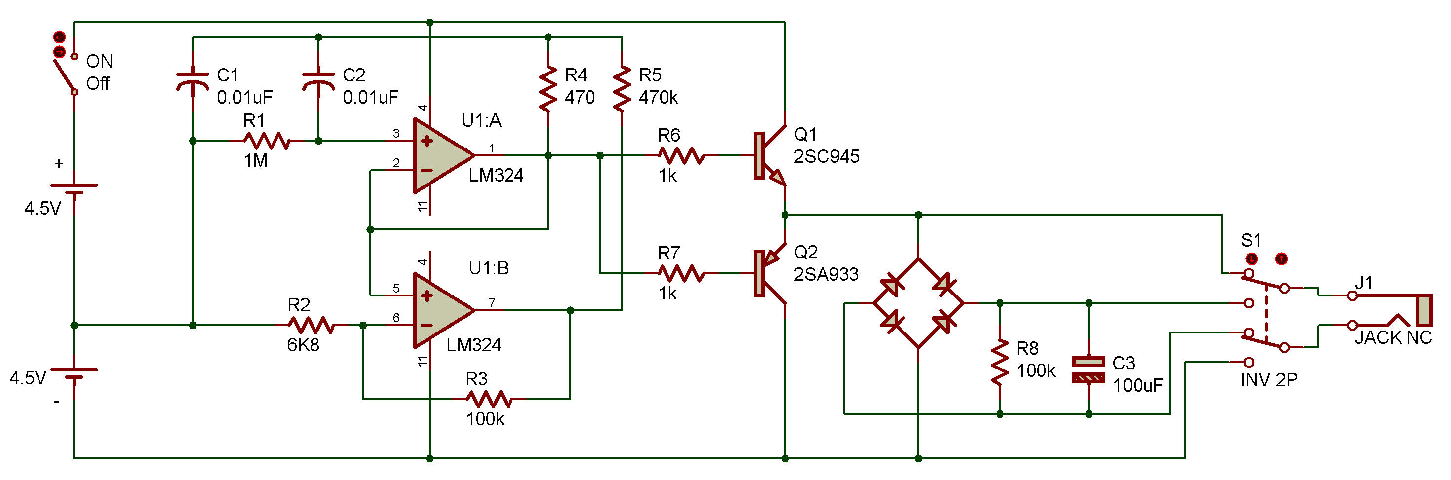
The circuit is formed a sine wave generator by adopting an OP amplifier U1A/U1B, resisters, and capacitors. The sine wave produced comes in the diode bridge circuit by way of SEPP (Single Ended Push-Pull) circuit which is configured by Q1 and Q2. We have determined the rectifier functions by simply hearing beep sound.

![]()