Non-inverting adder LM324
In this project, we're going to make an experimental adder using an operational amplifier. The circuit shown in the schematic is also called a "Summing Amplifier," because it sums up two or more voltages.
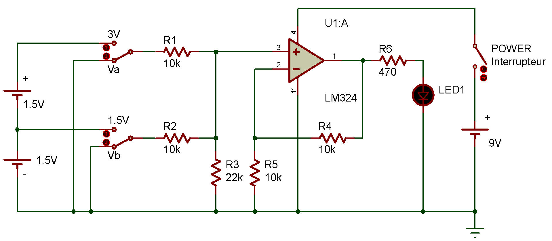
This circuit has two input terminals, Va and Vb. Input voltages applied to Va and Vb are summed up by operational amplifier IC 324 working as a non-inverting amplifier, and then displayed as an output. Let's get to the experiment.
Turn power ON, and connect the two input terminals to the (-) terminal. Since both input voltages are zero at this time, the output voltage is also zero and the LED doesn't light up.
See what happens when you leave Vb as it is and connect Va. The LED lights up, but it's not very bright.
Now connect Vb. What happens this time?
Observe how the LED changes its brightness when the voltage from the (-) terminal, V1 and V2 is applied. The way the LED changes its brightness lets you understand how the voltages are summed up by this circuit.

![]()