Digital timer
7400, 7476
We've built some timer circuits before (like Project Electronic Timer) but this one is different — it uses digital electronics.
The other timers have made use of the discharging rate of capacitors. Can you guess how this Project works from the schematic?
After you build this Project, turn the power ON.
The LED many or may not be on. Press the Key once and the LED should go out. Release the Key and watch the LED. After a few moments, the LED will light up.
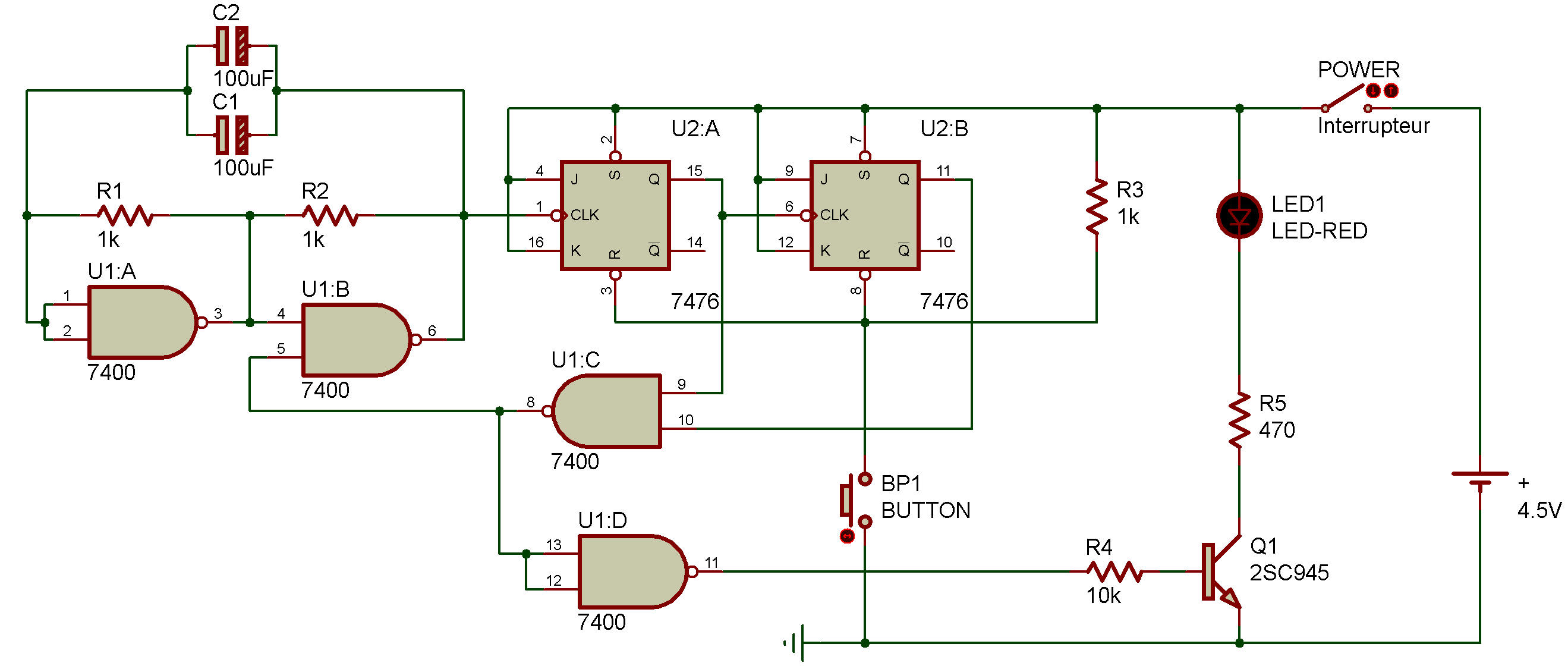
You can see this Project uses a NAND multivibrator and a J-K flip-flop counter circuit. When you press the Key, the counter is "reset" and the LED is turned off. When you release the Key, pulses from the multivibrator are fed into the clock input of the first J-K flip-flop.
After three pulses are input, the Q outputs of both flip-flops are 1. This 1 output goes to a NAND gate, producing a 0 output. The 0 output goes to another NAND gate, where it produces a 1 output.
This enables the Transistor to operate, lighting up the LED. You'll also notice that the 0 output also goes to the NAND multivibrator, where it stops the multivibrator from operating.
Try altering the operation of the multivibrator and see what effect it has on the timer. Can you think of any advantages this type of timer would have compared to circuits like Project Project Electronic Timer?

![]()