Whistle generating circuit
74HC00, 74HC02
In this project, you are going to generate a whistle of a steam train. The whistle from this project will be fine if it remind you of the pioneers' spirit in the good old days.
When you finish wiring, turn power ON and press S1. You should hear the whistle from the earphone. Does it sound just like a one you ever heard. If you wish to change the whistle, see Figure 1.
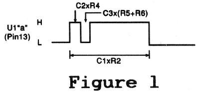
The length of the first "puff sound depends on the values C2 x R4. The silent interval after the puff is determined by C3 x (R5 + R6). The whole length of the "puff-toot" sounds is determined by C1 x R2. The whistle has off two consecutive tones: puff and toot.
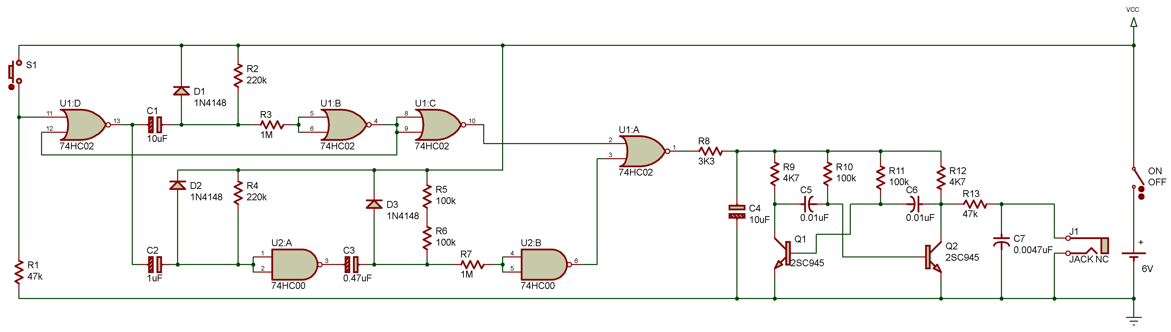
Take a look at the schematic diagram. The astable multivibrator comprising of Q1 and Q2 produces a "puff sound. U1 and U2 each form one-shot multivibrators, which are triggered when the key S1 is pressed. These one-shot multivibrators are used to generate the waveform shown in Figure 1 from the output of U1 "a".
When this output is at 1 (High), the astable multivibrator Q1/Q2 draws power, so it produces a "puff sound from the earphone.
When the same output is at 0 (Low), the astable multivibrator draws no power, so its oscillation stops. From the waveform in Figure 1, you'll see how the astable multivibrator works intermittently to generate the "puff-toot" sounds.

![]()