TTL line selector
7400
It isn't too hard Lo think of situations where we might want to send input data to two or more different outputs.
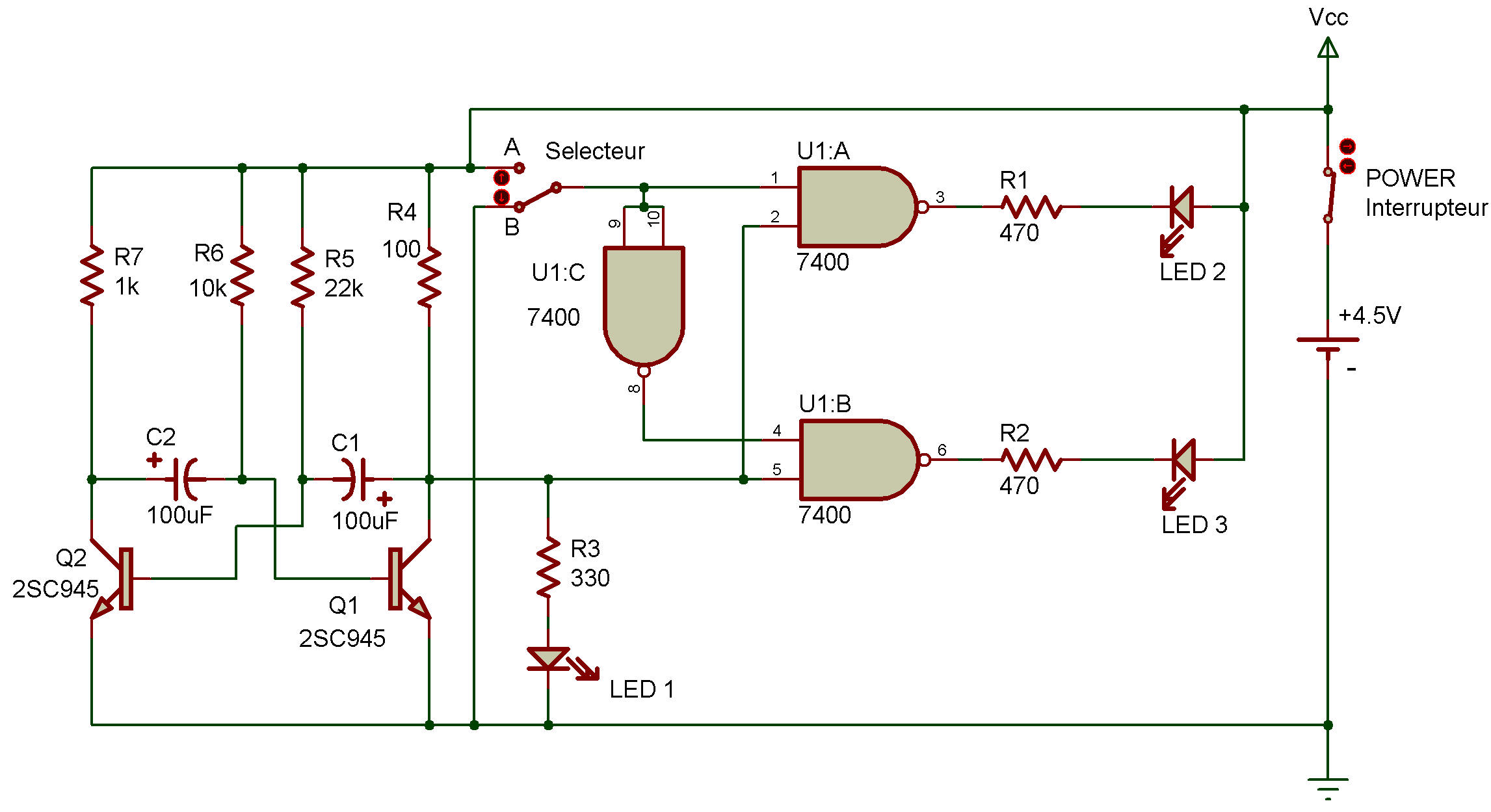
This Project shows how we can use a network of NAND gates to help us do just that. You can see that we use a multivibrator and three NAND gates in this circuit.
You can leave the Select Switch at either A or B when building this Project.
When you put power ON, you'll see that LED 1 is blinking. But what are LED 2 and LED 3 doing?
If the Select Switch is at A, LED 2 is blinking. But if the Select Switch is at B, LED 3 will blink.
As you can see on the schematic, setting the Select Switch to A or B controls the inputs to the two NANDs that light LED 2 or LED 3.
With the Select Switch at A, the NAND controlling LED 2 gets one steady input of 1. The output of the multivibrator supplies the other input. As the multivibrator's output switches from 0 to 1, the NAND controlling LED 2 also switches its output from 0 to 1.
The opposite happens when you set the Select Switch to B, Now the NAND controlling LED 3 gets a steady input of 1 so that LED 3 can go on and off according to the input from the multivibrator.
Now put on your thinking cap and try to follow the inputs from A and B of the Select Switch to LED 2 and LED 3. Notice the NAND gate serving as an input for the NAND controlling LED 3 what happens to it when you set the Select Switch from A to B?

![]()