DTL NOR gate
OR and AND aren't the only digital circuits we can whip up using DTL - and here's proof. If your memory's gotten rusty about how a NOR gate works, take a look back at Project Using the NOR gate before building this circuit.
While building this Project, be sure to set the Select Switch to B. After finishing the wiring connections, turn ON the power.
Is anything happening to LED 1?
Press the Key and see if there's any change in LED 1.
Release the Key and set the Select Switch to A. What happens to LED 1?
While the Select Switch is still set to A, press the Key and see if there's any change in LED 1.
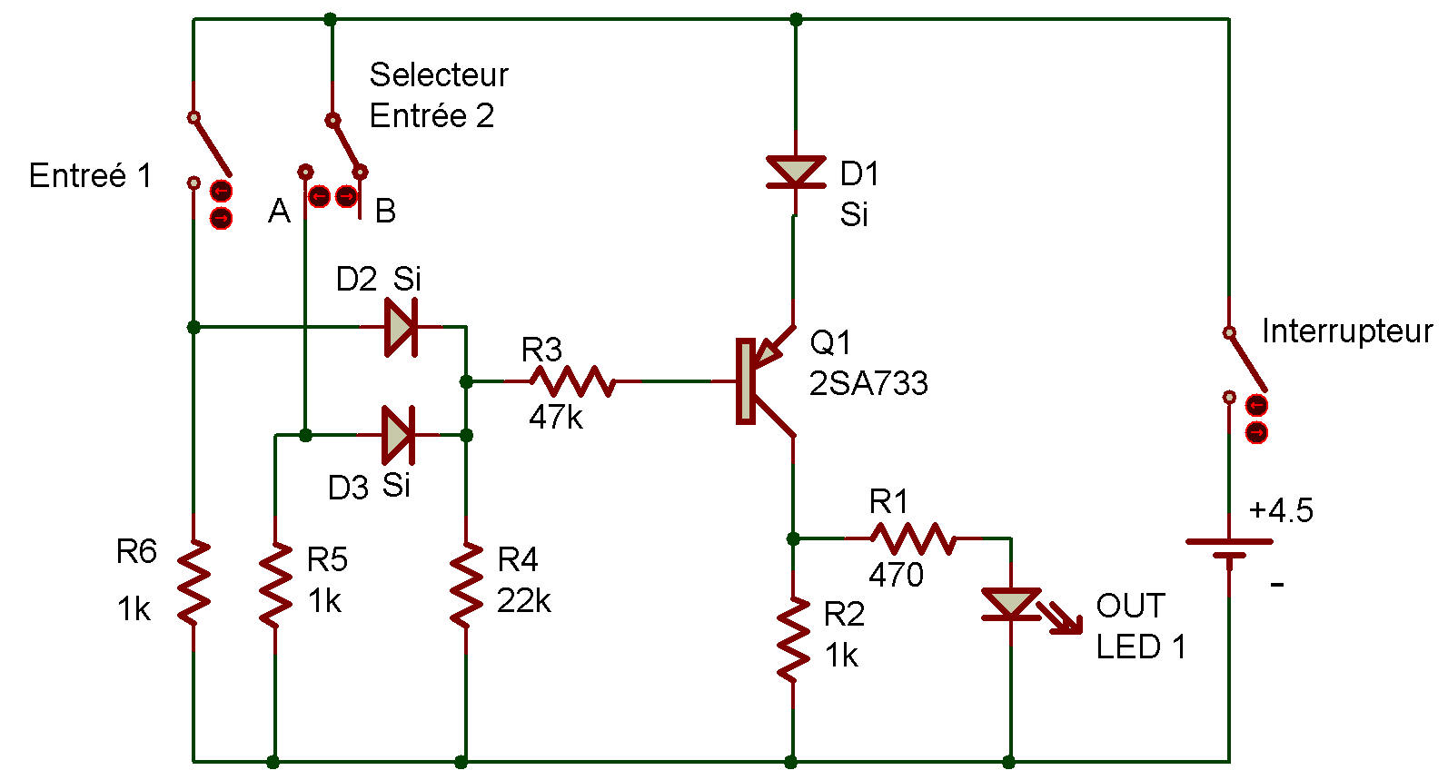
You can see how this circuit works by referring to the schematic. When the Key is not pressed and the Select Switch is at B?
Current can flow to the base of the Transistor and LED 1 will light. But if the Key is pressed or if the Select Switch is at A, the base is connected to the positive side of the Batteries. When this happens, the Transistor can't operate (since there's no current flow to the base) and the LED goes out.

![]()