C-MOS R-S Flip-Flop II
74HC76
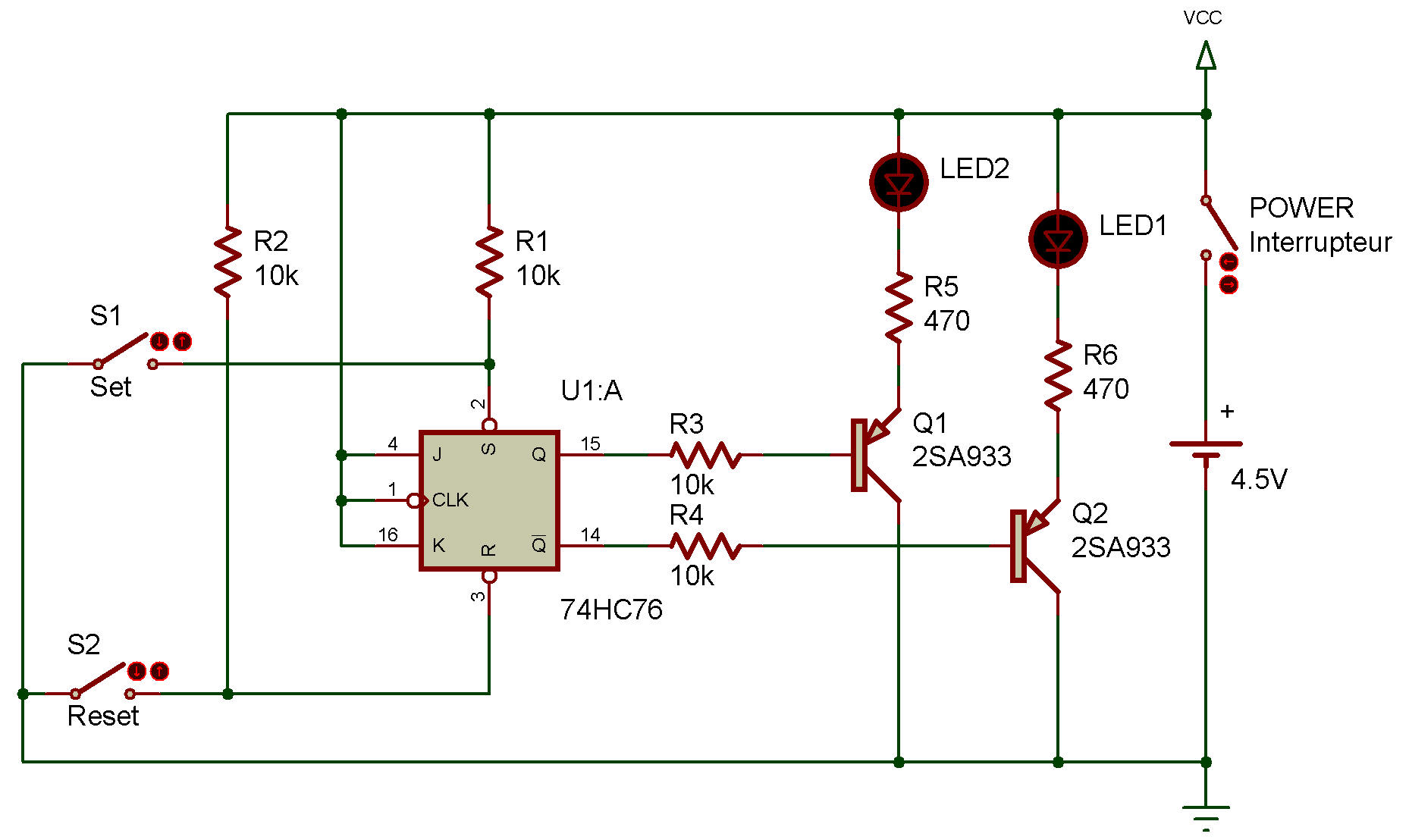
The integrated circuits 74HC76 is known as a "Dual J-K Flip Flop." Inside of that tiny IC are two J-K flip-flop circuits, like the one you built back project An R-S flip-flop!
ICs are true wonders, letting us use several circuits in a small space. Here's a project that lets you see how to use this particular one.
When you finish wiring this project, turn power ON. Press S1 and release it. Does anything happens to LED 1 or LED 2?
Now press S2 and release it. Is there any change in LED 1 or LED 2?
Can you figure out which terminal is the set input and which is the reset input? (Okay, here's a hint... do you remember what Q and Q7 stand for?)
This shouldn't have been too hard for you... IC terminal 2 is the set terminal while 3 is the reset terminal. You can see by the schematic that R and S aren't the only inputs to the flip-flop - there's also a J and K input. (So that's why it's called a J-K flip-flop!) What do you think these J and K inputs are used for?
Make some notes about what you think... because we're soon going to find out.

![]()