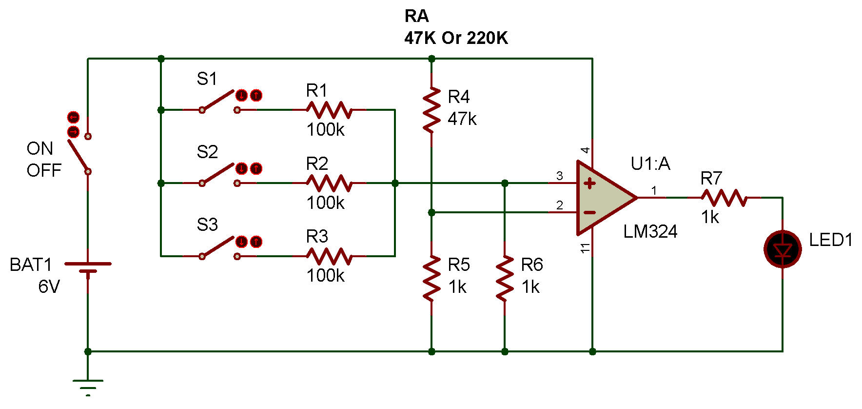
AND/OR circuit using op amplifier (AOP)
Les circuits logiques / Logic circuit
LM324
In this project, you're going to build an AND circuit and OR circuit using an OP amplifier.
The inputs to the circuit are the ON/OFF states of keys S1 - S3, and the output is indicated by lighting of LED 1.
Here, the ON state of a key corresponds to logical 1 on the input side, and the lighting state of LED 1 corresponds to logical 1 on the output side.
Build your AND circuit by connecting a 47k resistor to RA.
Being sure that keys S1 - S3 are all in the OFF position, turn power ON. Let's check that this circuit works as an AND circuit.
Press ON the keys S1, S2, and then S3. What happened?
As you've seen, LED 1 lit when all keys were ON. In an AND circuit, the output is 1 when all inputs are logical 1s.
Next, turn power OFF and change RA with 220k to build OR circuit.
This time, you press ON all switches and then turn power ON. Press OFF the keys S1 - S3 one after another. Check that your circuit acts as an OR circuit. You've noticed that all keys were OFF when LED 1 lit. In an OR circuit, the output is 1 (the LED lights) when any one of the inputs is logical 1 (any key iis ON).
In our circuit, the OP amplifier is used as a comparator. It compares the input voltage developed with the ON/ OFF combination of the three switches, relative to the reference voltage determined by RA and R4. Lighting of LED 1 is controlled with the difference between the two voltages.

![]()