Logic "AND" with LED Display
The purpose of this project is to study a logic AND circuit as used in computers. The readout is connected to display the letter H when terminals A and B are both connected to terminal H (121). These letters all have logic significance; where, A and B are the logic inputs, H is a logic high (ON), and L is a logic low (OFF). The Truth Table for the logic AND function is as follows:
|
A |
B |
Output |
|
L |
L |
L |
|
L |
H |
L |
|
H |
L |
L |
|
H |
H |
H |
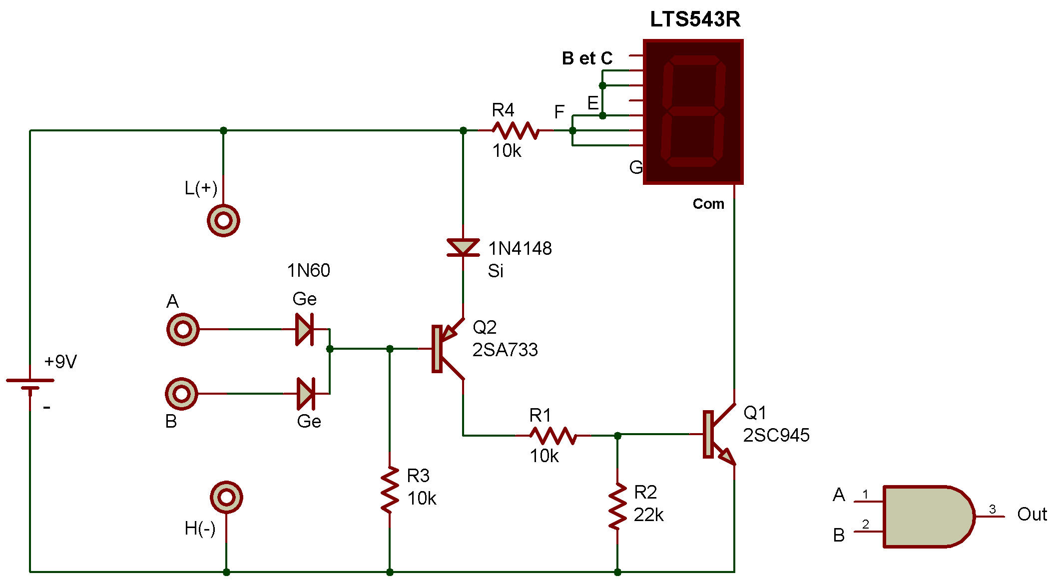
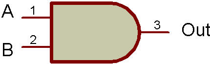
Expressed in words, both A and B must be high for the output to be high. The logic symbol is also shown along with the Schematic.
This function may also be written as
 , or as
 , or as
 .
.
Circuit operation is as follows:
Whenever either one or both inputs are on L, the low forward voltage drop of either germanium (Ge) Diode keeps the PNP Transistor from turning ON. With this Transistor OFF, no bias is supplied to the base of the NPN so that it is OFF, also. This causes the readout to remain dark.
Now if both inputs are on H, both Diodes are reverse-biased across the 10K Resistor and perform no function. This 10K Resistor provides bias to the base of the PNP to turn it full ON. The NPN is also biased full ON at this time with the current flowing through the 10K in it's base circuit, the PNP and the silicon (Si) Diode.
With the NPN on, current can flow to the readout to light the LED (forming the letter H). The silicon Diode helps to insure that the PNP is off whenever either Diode's (Ge) forward voltage is present at the base. The 22K Resistor insures than any small amount of leakage current from the PNP in the OFF state, doesn't turn ON the NPN.
Your VOM voltmeter may be used across C and E to verify the ON and OFF characteristics of the Transistors. Because the two logic states are H and L, the input terminals should always be connected to one of these terminals (H or L). For this particular circuit open (not connected) input terminals are the same as a high input.

![]()