Toy Organ circuit using transistors
Circuits Divers / Various Circuits
| Jouons avec un
circuit d'orgue jouet tout simple. Croyez-le ou non, on peut créer soi-même un circuit de piano simple. |
Let’s play
with a simple toy organ circuit. Believe it or not, we can create a simple piano circuit by ourselves. |
| Qu'est-ce
qu'un orgue jouet ? Un circuit d'orgue jouet, ou orgue monophonique, est un circuit qui produit des sons en fonction de la pression exercée sur une touche. On ne peut appuyer que sur une touche à la fois. |
What is a
toy organ? A toy organ circuit or a monophonic organ is a circuit that generates tones according to the pressing of a key. The button can only be pressed one at a time. |
| Comment ça
marche ? Ce circuit génère la fréquence sonore à la manière d'un multivibrateur astable. Ce type de circuit nous est familier grâce aux circuits clignotants à deux LED. (Flip-Flop, multivibrateur bistable) Principe de base Imaginez que l'on connecte un haut-parleur à une LED. On entendra alors un « tic-tac » lorsque la LED clignote. Et si l'on augmente la vitesse de clignotement de la LED, la continuité du son entendu augmentera jusqu'à produire le son d'un buzzer classique. |
How does it
work This circuit generates the sound frequency in a way of an astable multivibrator. We are familiar with this sort of circuit from the two LED flasher circuits. (Flip-Flop, bistable multivibrator) Basic thought Suppose we connect a loud speaker with an LED. We will hear the “Tik…Tik” sound as LED flashing. And when we increase the speed which the LED flashing, the continuity of the sound we hear will increase to the point of becoming a normal buzzer. |
| Le niveau ou
la fréquence du son dépend des condensateurs C1 et C2, ainsi que des
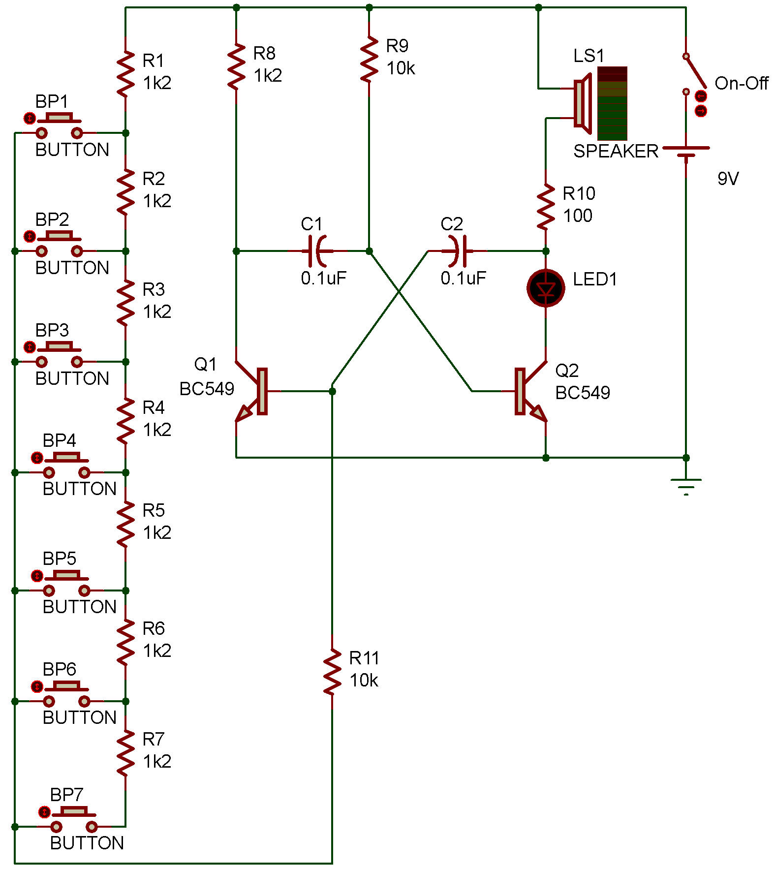
résistances R8 et R9. Dans le cadre d'un circuit simple, Il est préférable de modifier R8 et R9. Si l'on ne touche pas à R8 et que l'on modifie R9, le son sera également modifié. La valeur de R9 peut être contrôlée par le clavier. Nous avons besoin de 7 tonalités différentes, une pour chaque clavier. Examinons donc le circuit d'un simple bouton-poussoir. Cet ensemble de résistance et d'interrupteur représente R9 dans le circuit. |
The tone level
or frequency is based on C1, C2, and R8, R9. In terms of a simple circuit design. We better change R8 and R9. If we leave R8 alone and instead modify R9, it will also change the tone. Which R9 can be controlled by the keypad. We need 7 different tones for 7 different keypads. So, let’s take a look at the simple push-button circuit. These set of resistor and switch represent R9 in the circuit. |
| Voici
comment cela fonctionne : Si l'on appuie sur le bouton BP1, le courant circule en série à travers R1, BP1 et R8. La résistance totale est alors égale à : R1 + R8 (1,2 kΩ + 10 kΩ) = 11,2 kΩ. En revanche, si l'on appuie sur BP5, le courant circule à travers R1, R2, R3, R4, R5 et BP5 jusqu'à R8. La résistance totale est donc égale à : (1,2 kΩ + 1,2 kΩ + 1,2 kΩ + 1,2 kΩ + 1,2 kΩ + 10 kΩ) = 16 kΩ. En résumé, la résistance totale prend en compte la résistance de chaque composant traversé, plus R8. Bien entendu, plus la résistance est faible, plus la fréquence est élevée, et inversement. |
They work
as follows. If we press the button BP1 the current will flow through R1, BP1 to R8 in series. Making total resistance equal to R1 + R8 (1.2K + 10K) = 11.2K. But when BP5 is pressed the current will flow through R1, R2, R3, R4, R5, and BP5 to R8. So, total resistances equal to (1.2K + 1.2K + 1.2K + 1.2K + 1.2K + 10K) = 16K. To sum up, the total resistance will take account of each resistor it passed, plus R8. Of course, the lower the resistance, the higher the frequency, and vice versa. |
|
Fonctionnement d'un circuit d'orgue jouet Observons maintenant le circuit complet. Comprenons le principe de fonctionnement de ce circuit, qui est celui d'un générateur haute fréquence. Lorsqu'on alimente ce circuit, il ne réagit pas immédiatement. Mais si l'on appuie sur l'interrupteur BP1, le circuit se met en marche. Le courant circule alors à travers R9 jusqu'à la borne B de Q2. Q2 démarre en premier, faisant circuler le courant à travers BP1, R10 et LED1. En maintenant BP1 enfoncé pendant quelques secondes, le courant circule à travers R1, BP1 et R11, et charge C2 jusqu'à sa pleine capacité. Q1 se met alors en marche, laissant passer le courant à travers R8 jusqu'à C1. Ce dernier se charge, ce qui diminue la tension de polarisation de Q2 jusqu'à ce qu'il s'arrête. À ce moment-là, la LED1 s'éteint, indiquant qu'aucun courant ne circule vers BP1. Lorsque le condensateur C1 est complètement chargé, le courant circule vers la borne B de Q2, ce qui provoque le redémarrage de Q2 et l'arrêt de Q1. Ils continuent de fonctionner alternativement, générant ainsi une fréquence. Si l'on actionne d'autres interrupteurs, la résistance totale varie en fonction du nombre de résistances, comme expliqué précédemment. |
How toy
organ circuit works Now, let’s look at the whole circuit. And understand the working principle of this circuit as a high-frequency generator circuit. When we power this circuit, it will not do anything right away. But if we press switch BP1, the circuit will begin the work. By having the current flow through R9 into B of Q2. It makes Q2 begin the work first, making the current flow through BP1, R10, and LED1. By pressing BP1 for a few seconds, causes the current to flow through R1, BP1, and R11, and charge the C2 until fully charged. Then, Q1 will start to work, letting the current flow through R8 to C1. And charging it to lower the bias voltage at Q2 until it stopped working. Right now the LED1 will go out indicating that there will be no current flow to BP1. When the C1 is fully charged the current will flow to B of Q2. Causing Q2 to start up again, and Q1 will stop working. They will continue to work alternately like this, creating frequency in the process. If we press on other switches the total resistance will change depending on the number of resistors as we have talked about before. |
![]()