Three phase oscillator LM324
In this project, you're going to generate three signals which are same in frequency but different in phase from one another. The different signals can visually be checked on three LEDs.
When you finish wiring, turn power ON.
Watch the three LEDs to see how they change. LED 1, LED 2, and LED 3 repeat flashing for fixed intervals, each slightly overlapping with the next. Actually, the phases of three signals differ 120° each other. The way the LEDs light shows you that a three-phase oscillator is operating.
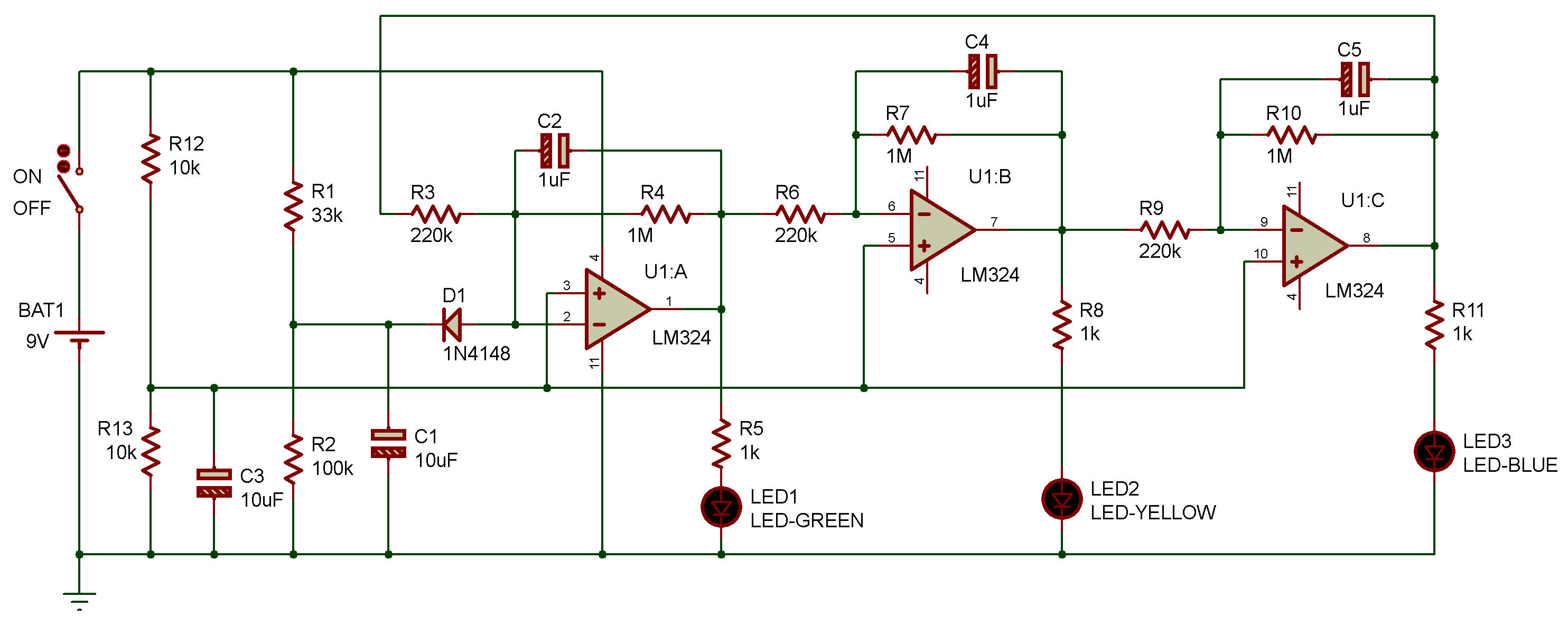
This circuit uses three OP amplifiers, which serve as inverting amplifiers. For each amplifier, the negative feedback section is connected with a 1-megohm resistor and a 1uF capacitor in parallel, so that the output signal has a phase difference of 120° relative to the input signal.
The three amplifiers comprise a three-phase oscillator, with a total of phase difference of 360°. The diodes control the amplitude limit of signals and the phase differences in the loop.
| Bill Of Materials For Three phase oscillator | ||||||
| 13 Resistors | ||||||
| Quantity: | References | Value | ||||
| 1 | R1 | 33k | ||||
| 1 | R2 | 100k | ||||
| 3 | R3, R6, R9 | 220k | ||||
| 3 | R4, R7, R10 | 1M | ||||
| 3 | R5, R8, R11 | 1k | ||||
| 2 | R12, R13 | 10k | ||||
| 5 Capacitors | ||||||
| Quantity: | References | Value | ||||
| 3 | C1, C3 | 10uF | ||||
| 2 | C2, C4, C5 | 1uF | ||||
| 1 Integrated Circuits | ||||||
| Quantity: | References | Value | ||||
| 1 | U1 | LM324 | ||||
| 1 Diodes | ||||||
| Quantity: | References | Value | ||||
| 1 | D1 | 1N4148 | ||||
| 5 Miscellaneous | ||||||
| Quantity: | References | Value | ||||
| 1 | BAT1 | 9V | ||||
| 1 | LED1 | LED-GREEN | ||||
| 1 | LED2 | LED-YELLOW | ||||
| 1 | LED3 | LED-BLUE | ||||
| 1 | ON | OFF | ||||

![]()