Regulated Power Supply
The purpose of this project is to study an electronically regulated power supply as used in computers. A supply such as this is used to hold the DC output voltage steady at a fixed value such as 3.6V or 5.0V..
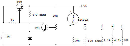
Without a constant, accurate voltage such as this, many computer circuits could not operate properly. The electronic voltage regulator circuit uses all of the Schematic components between the Battery and the Meter circuit in this project.
The Resistors from 100 ohms to 10K are used as loads on the power supply. The Meter circuit, composed of the Meter and 10K Resistor has a full-scale voltage calibration of about 2.7 volts. This Meter circuit is included to show that the voltage change is not affected much by this wide range of loading caused by using the four different load resistances.
Connect the circuit and adjust the Control for a Meter reading of about 5 or 6 on the top scale.
Now use the lead wire from terminal T1 as a Probe and touch it to each of the terminal numbers and load Resistors as listed on the Schematic. The voltage as indicated on the Meter should not change much at all. Only the 100 ohm load, which causes a much heavier current flow than any of the other Resistors, should cause more than a couple of percentage points of change.
If you have a V0M you can use it to measure the different load currents. Take our word for it, a power supply delivering this voltage without the use of a regulator circuit like this would allow the output voltage to change at least 10% or more.
The 2SA(1) is called a "comparator". It compares the voltage at its emitter (E) with that at its base (B).
The 2SA(2) is called the "series pass" Transistor because all the current of the load must pass through this series device from collector (C) to base (B).
The 1K Resistor supplies the current to bias the 2SA(2).
More current flows than what is required so that the 2SA(1) can also pass some current during normal operation.
The 470 ohm Resistor and (Si) silicon Diode provide a constant voltage of about 0.7V for the emitter of the 2SA(1).
Operation is as follows, for a condition of heavy loading that would tend to pull the output voltage down. The 2SA(1) base would tend to go down, but because the stage is operating as a common emitter stage, its collector voltage (and therefore the 2SA(2) base voltage) would tend to go up.
Now because the 2SA(2) acts as an emitter follower stage, the output would also tend to go up. This opposes the original tendency for the output to go down so the output remains about constant. Operation for the condition where the output tends to go up due to light loading, is the opposite in direction of change, but the same in effect — stabilized output voltage.

![]()