PNP transistor switch
We're all familiar with mechanical switches like the power switch; the transistor can do the same as we saw in last projects. These are called electronic switches.
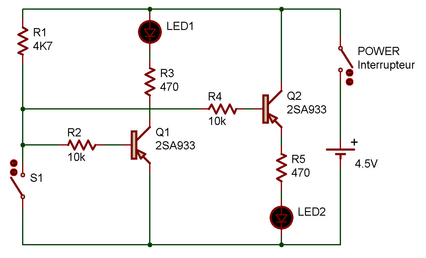
First let's try an electronic switch using two PNP transistors. The schematic shows you that the LEDs are connected to the emitter of Q1 and to the collector of Q2. Let's see how these transistors work as switches.
When you finish wiring up the circuit, switch power ON. Do any of the LEDs light up?
They don't, do they?
Now press S1, and both LEDs light up. Ib1 and Ib2 flowing at this time to S1 are very small, but can switch the large currents Ie1 and Ie2 that flow to light the LEDs.
Oh, by the way, we expressed the emitter-to-base current for each transistor as Ib1 and Ib2, and the emitter-to-collector current as Ie1 and Ie2.
The I's are the conventional symbol for current, and we added suffix b for current flowing into the base, e for current flowing into the emitter. We will use more of such expressions in this manual, so get used to it.
Anyway, Ib1 is far better than "emitter-to-base current for Q1," isn't it?

![]()