
Transistorized DC Voltmeter
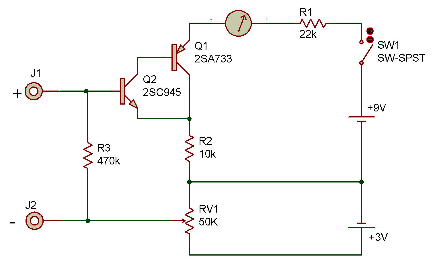
This project shows how a bridge circuit and a high-gain amplifier can be used together as a low-range DC voltmeter. A DC voltmeter which uses an amplifying device like this is called an electronic voltmeter. The VTVM (vacuum tube volt meter) is probably the best known electronic voltmeter.
Operation of this circuit is as follows:
1) After the wiring is complete, adjust the Control so the Meter gives a reading of 1 on the blue scale. The reading of 1 will indicate 0 volts on this Meter. This setting is necessary to keep a small amount of current flowing to the Transistor at all times. This will improve the linearity of the Meter (make each segment of the scale represent the same amount of voltage).
Note: Each segment of the blue scale will represent about 0.25 volts with this Meter. A 1.5 volt battery should register about 7 (6x0.25, plus 1 for the beginning Meter setting).
2) Connect the Probe wires to the DC voltage to be measured (it must be less than 2 1/4 volts for this circuit). Make sure you observe the correct polarity (+ and -).
To change the Meter for measuring lower voltages, replace the 10K resistor with a lower value (4.7 K or 1K). The amount of voltage for each unit on the scale will decrease in proportion with the resistance.
For example, if you decrease the 10K Resistor to a 4.7K (about half the resistance), each unit on the scale will represent about half of the original 0.25 volts (0.125).
CAUTION: A very sensitive Meter can be damaged by even a small voltage. Use the information above to calculate the voltage limit of the Meter before you use it.
The 2SC and 2SA Transistors are connected in a way that produces a very high gain (amplification). This special way of connecting transistors is called "Inverted Darlington".
Another Version
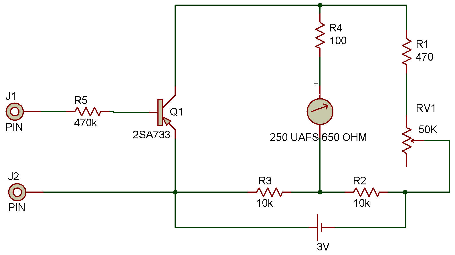
![]()