
Series Type Ohmmeter
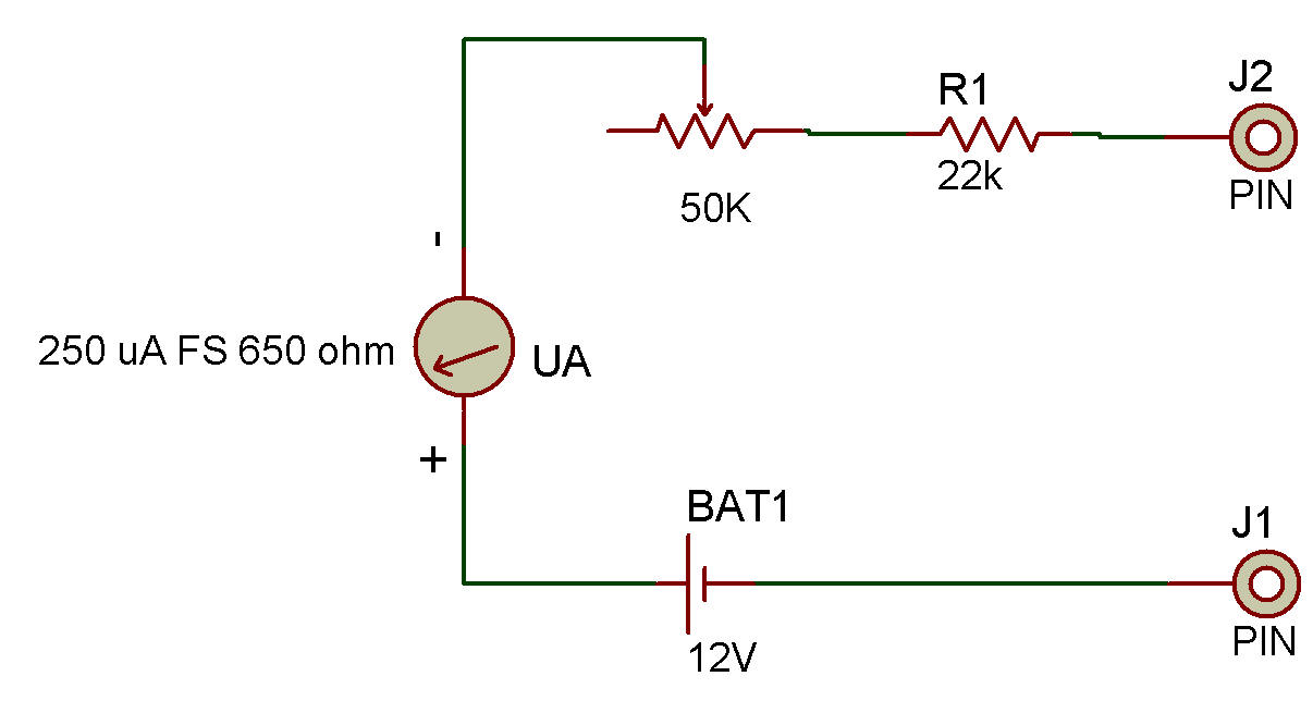
The purpose of this project is to build and test a series type ohmmeter and in the process learn more about resistance. If you own a VOM it probably has a circuit very much like this to measure resistances. This circuit uses both 12 volt Batteries to obtain measurement of high resistance.
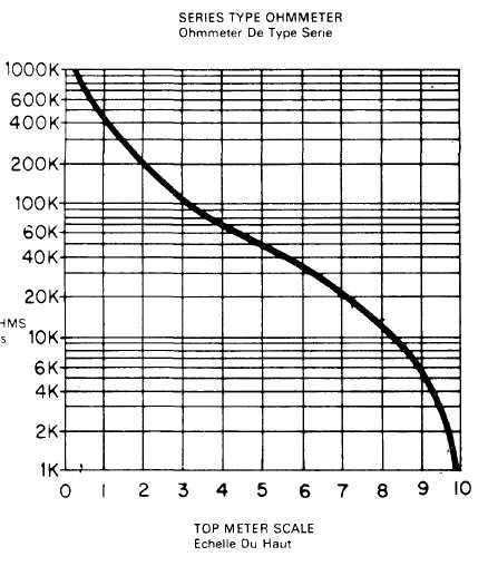
The Meter may be considered a current detector which can be calibrated in resistance because the voltage is a constant value of 12 volts. This is justified by Ohm's law where I = E/R, so if E (voltage) is not changed, I (current) is inversely proportional to R (resistance). A graph is included below to change the Meter's blue scale calibrations directly to K ohms. The letter K means "thousands" so a resistance of 22K is 22,000 ohms. This amounts to a shorthand method that eliminates writing zeros. The procedure for using this ohmmeter is as follows:
1. Touch the Probes together (zero resistance between the probes) and adjust the 50K Control for a full scale Meter reading (10 on the scale).
2. Without disturbing the Control as adjusted above, connect the Probes across the resistance to be measured. Make sure there are no parallel paths of resistance (including your hands) or results will be incorrect. Also, make sure no voltage is present across the resistance or the Meter may be damaged.
3. Locate the Meter reading along the bottom of the graph. Go vertically up from there to the curved line. This point on the curve indicates the resistance. Read the resistance value from the resistance scale directly to the left of this point on the curve. An ohmmeter such as this is one of the most valuable tools a repairman has to check for defective parts. Use the ohmmeter you have just made, and measure some of the following parts.
1. Resistors: They should be relatively close to their market value.
2. Diodes: With one ohmmeter connection polarity you should obtain a low resistance; with the opposite polarity, a high resistance.
3. Transistors: Between C-B and E-B junctions you will get the same results as with Diodes. (An exception to this is the E-B junction of silicon Transistors which gives intermediate resistance in the high resistance polarity. This does not indicate a fault.) Between C-E terminals you will see a high resistance with both polarities.
4. CdS photo cells: Resistance depending on light level.
5. Capacitors: Values above 0.01 uF indicate charging (displacement) current before showing a very high resistance (virtually infinity on this meter). Electrolytic Capacitors which are marked with voltage polarity will show near infinity resistance (after charging) when correctly polarized and intermediate resistance when improperly polarized.
Always discharge Capacitors completely with a short circuit before attempting to measure their resistance. In case you are interested in the formula which is used to determine the resistance from the Meter, here it is:
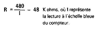
where I is the I blue meter scale reading.
Notice that the most accurate range of resistances measured with this meter is between 2K and 900K ohms. The Shunt-Type Ohmmeter project is next and is suitable for lower ranges of resistance see Testers Setion.
![]()