
Transistor Switcher 1
![]()
The purpose of this project is to further study the switching action of bipolar Transistors used to turn ON a readout device. The 2SC Transistor at the bottom of the circuit is continually turned ON by the positive base voltage supplied through the 47K limiting Resistor. The base-to-emitter voltage of a Transistor which is biased ON is only a few tenths of a volt, so almost all the 9V of the Battery goes through the 47K Resistor. The base current may then be calculated by Ohm's Law:
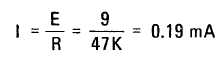
If the 2SC Transistor has a current gain of 100, then the amount of collector current which can flow is 100 X 0.19 = 19 mA. Of course, a higher current gain would allow a larger collector current to flow, and a lower gain, a lower current.
The 2SA Transistor at the top of the Schematic is turned ON through the 22K limiting Resistor and the ON-OFF Switch. Because this resistance is about half of the 47K, the current supplied to the base of the Transistor is about twice as much as that supplied to the 2SC.
The 2SA Transistor is therefore said to be more ON or "harder ON" than the 2SC. A switching Transistor which is not ON hard enough cannot allow the required circuit current to flow in its collector circuit. The result is an excessive current across the Transistor collector-to-emitter, insufficient voltage available for the readout to give adequate illumination and possible overheating of the Transistor.
Hook up the circuit and check operation to see that the numeral "1" can be displayed with adequate brilliance.
Transistors may be turned ON harder by increasing the base current. This is accomplished by decreasing the limiting resistance in the base circuit. Don't decrease the resistance too far, or the Transistor will be burned out!
Now change both Resistors to 10K and repeat the above experiment. The illumination should not drop off much with the Transistors ON this hard. If much change does occur, check the 9V Battery. It's probably weak.
With your VOM you can check the voltage drop across collector-to-emitter on each Transistor to determine when it is not turned ON hard enough to keep its voltage below 0.5V or so. From this project we can see that whenever the base-bias is present the Transistor is ON, but full ON is indicated by the low voltage across the collector-to-emitter. A Transistor which has maximum collector-to-emitter voltage is in the OFF state.
![]()