
Transistor Switcher 2
First, notice the similarities in this circuit with the circuit of the previous project see Transistor Switcher 1 in Switches Section.
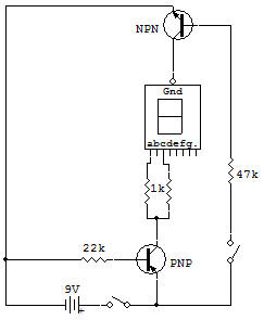
The only difference between these two circuits is the place where the switch is set. In this project the switch is in the base circuit of the NPN transistor for controlling the input common cathode of the LEDs. This can then be seen as a cathode control of the LED, while the previous project is an anode control.
Resistance of 22K puts the PNP transistor on at all times while the resistance of the NPN 47K puts on just while the key is closed.
These resistors have a value sufficiently low to allow proper switching transistor with some segments of the connected LEDs. The ability to turn on the LED with either transistor or the upper or the lower transistor seems more important now. But for someone who has to create these complicated computer circuits, this is a good way to control circuits without a host of additional transistors, etc.
Have you noticed at this point that the transistors switch as soon as the switch itself. This is a characteristic of transistors that make functions with such speed. Transistors are many times faster than relays or manual switches. Other experiments demonstrate how a switching delay can be obtained by using other components.
![]()