Automatic Light Activated Radio
Here is a radio which turns on at dawn and off at night. This little sensitive to radio two transistors is controlled by a relay circuit which is controlled by a photoelectric cell.
The relay circuit uses most of the current from the battery, so if you just want a good radio, you can replace the relay circuit by a section of the slide switch.
The driver circuit includes a relay sensitivity control to the desired level of light required to turn on the radio. You can adjust the controls for you to wake up at dawn - or after the sun started this clock radio .
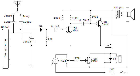
Note the silicon diode across the relay field. Such a diode is normally included in the design of highly reliable equipment. It does its job when the relay is at rest. During normal operation of the relay, the diode is reverse biased when it acts as an open circuit. When the transistor is off, the magnetic field of the relay tries to suddenly collapse and produces a high peak voltage appearing across the transistor. When the diode is included, becomes polarized in the right direction by the induced voltage of the magnetic field collapses and limit the voltage to less than one volt, thereby protecting the transistor.
The radio section of this project requires an antenna system. The detector is a common circuit detection diode. The transistor amplifier uses two-stage neck beach RC (resistor-capacitor) and the fixed base bias current.
There is no volume control so you can change the volume by changing the antenna connection or slightly tuning the next post. This receiver is a good receiver even if it has only two transistors.
If you have a VOM, this is a good project to measure voltages of the circuit. Q1 should have a voltage across C-E of between 1 and 4 volts. The current of the Q2 collector is between about 1 and 4 mA. The current of Q3 collector is between 6 and 18 mA when the relay is energized.

![]()