
Pulse Oscillator Tone Generator
This project is a pulse-tone oscillator which is adjustable in frequency to obtain a wide range of notes. With practice you should be able to play tunes on it, similar to an electronic organ.
To play a tune, adjust the Control to the proper note and press the Key momentarily. Readjust the Control for the next note and again press the Key. After some practice you should be able to play some simple tunes. You will also be able to slur between notes, like a trombone. This circuit is such a typical pulse-tone oscillator, we will explain the circuit in some detail.
Like all oscillators, it meets the two basic requirements for oscillations: a gain greater than 1 (1 being the input) and regenerative feedback. It is the feedback control circuit we will look at specifically.
First, review of basic Transistor characteristics: Any current flowing through the Transistor must pass through the emitter against the direction of the arrowhead. Collector current cannot flow unless there is also base current (unless resistance is in series with the collector to limit the collector current).
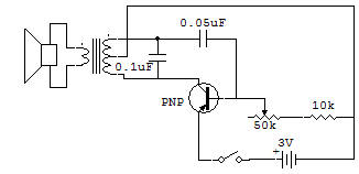
Now we will try to show how the 0.05uF Capacitor is quickly charged to about 4V, and how this charge must leak off some before it will allow the Transistor to turn ON and repeat the cycle. It will help you if you use different color pencils or pens to draw arrows around the Schematic diagram to identify the following currents.
When the Key is first closed the base bias current flows around the loop formed by the Battery, 10K, 50K, Transistor B-E and Key. (Current always flows from negative to positive.) The above base bias current causes collector current to flow around the loop formed by the 3V Battery, lower half of the Transformer winding, Transistor C-E and the Key.
The current flowing in the Transformer induces (by transformer action) a current around the loop formed by the top Transformer winding, the 0.05uF, Transistor B-E, Key, Battery and back to the Transformer center tap. This current quickly (in less than 0.0001 seconds) charges the 0.05uF to about 4V or so with a polarity which is negative on the Transformer side and positive on the Transistor base lead side.
The Speaker output pulse is obtained only during the time current flows in the Transformer. The charging of the 0.05uF stops because the induced voltage from the top half of the Transformer winding stops, due to Transformer core saturation. As soon as this current stops, the Capacitor begins to charge.
As soon as the discharge begins, it turns the Transistor OFF because the Capacitor voltage is higher than the Battery voltage and has reverse polarity voltage applied to the base of the Transistor. All Transistor junctions act like open circuits at this time. The Capacitor discharges around the loop formed by the top Transformer winding and the 10K and 50K. When less of the 50K resistance is in the circuit, the discharge is faster, so the process is repeated at a faster rate (higher frequency).
As soon as the 0.05uF Capacitor discharges to slightly below the 3V of the Battery, the above cycle of events is repeated. The best way of obtaining the above circuit action is with the use of an oscilloscope. Eventually you will want to add an oscilloscope to your test equipment, because no other instrument can show you as much about circuits as it can.
![]()