
Upper/lower limiter circuit using op amplifier LM324
In this project, you are going to make a limiter circuit. The limiter clamps or slices the voltage at the limiting level.
When you finish wiring the project, turn the select switch to up position and turn the control volume fully counterclockwise. Set the slide switch to ON.
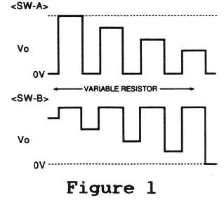
Then, you can see LED 1 starts blinking. As you turn the control volume clockwise slowly, the blinking LED 1 becomes dimmer, which is illustrated in Figure 1.
Let's make an opposite operation. Turn the control volume fully clockwise and turn the select switch to down position. Then, LED 1 starts blinking just like you have turned the control volume fully counterclockwise.
OK, let's turn the control volume slowly counterclockwise. As you turn the control volume counterclockwise slowly, the blinking LED 1 becomes brighter, which is illustrated in Figure 1.
As you can see, this circuit controls the brightness of blinking LED1.
The circuit is formed by an oscillator U1A that generates a square waveform with a frequency of 1 to 2 Hz and a voltage limiter circuit (U1B and two diodes). The limiter circuit controls the waveform output from the oscillator.
The control volume connected to U1B varies the voltage to be limited. The select switch changes the direction of diodes, which determines the scope of limits; either upper limit or lower limit.

![]()