Delayed timer LM324
In this project, we're going to make an experiment on a delayed timer, using this operational amplifier and the CR time constant. The CR stands for, as you might suspect, capacitor and resistor.
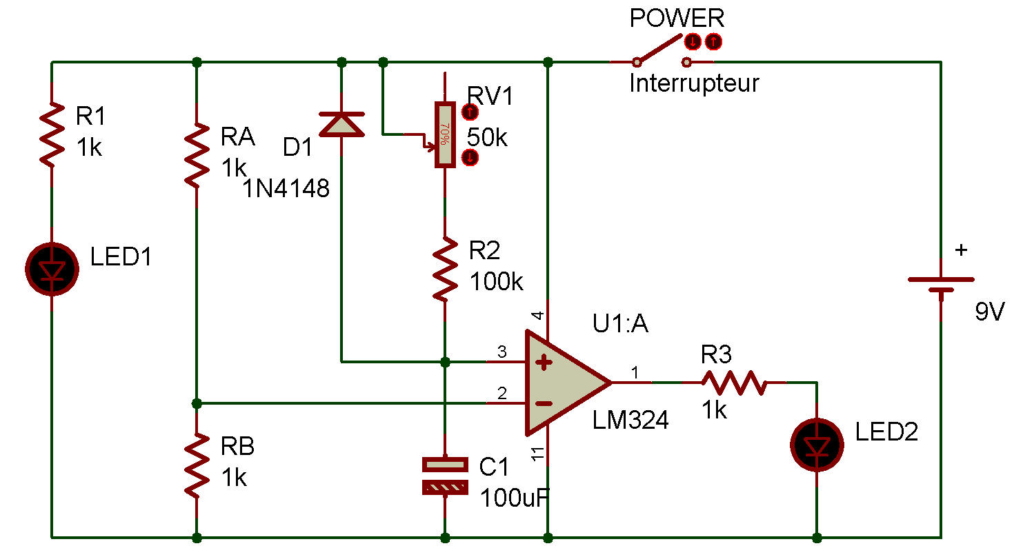
The - terminal of the operational amplifier has a voltage of about 4.5 V, obtained by RA and RB. This is the comparator's reference voltage.
The + terminal of the comparator is connected to C1. C1 is charged by the series resistance of R2 and the control volume. The charging speed goes down if the resistance is large, and gets faster if the resistance is small. The delay time is set by this charging speed.
To use this project, set the control volume fully clockwise. Turn power ON:
LED 1 lights up first and LED 2 also lights up about 7 - 8 seconds later. This 7- to 8-second time difference is the delay time set by the CR time constant.
Now, turn power OFF, set the control volume fully counterclockwise (minimum resistance position), and see what happens when you turn power ON again. LED 2 again lights up later than LED 1, but how many seconds later?
Now you see what this project's demonstrating.

![]()