2 inputs alarm
7400, 7476
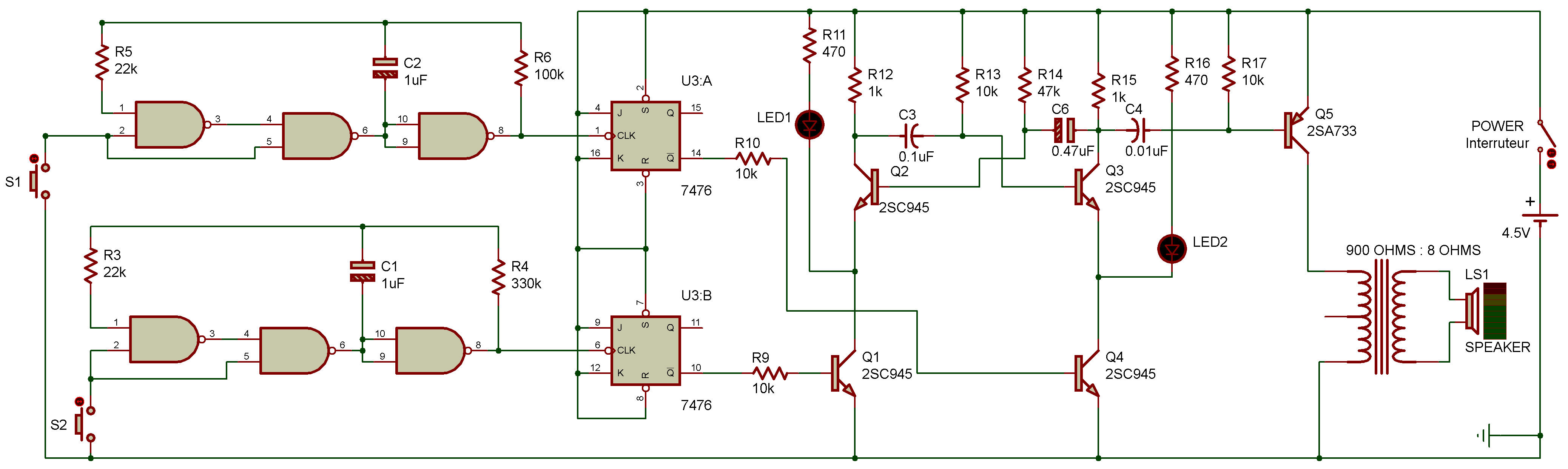
A quick glance at the schematic shows this project uses both a J-K flip-flop and an astable multivibrator.
The astable multivibrator produces a sound from the speaker and you'll also notice LEDs 1 and 2 light up at different rates.
Both S1 and S2 are used here to control the inputs to the J-K flip-flop circuits. Your job is to select that combination of switch settings that lets both LEDs light and also produce a sound from the speaker.
Push the S2 to generate pulses for the J-K flip-flop. You see LED 1 flicker but hear no sound.
Push S2 again: the LED 1 change condition, on or off. Now try press S1.
You'll now see LED 2 flicker. Release it, and the LED 2 stays either on or off. If you manage to set the switches to the correct positions at the right time you'll light both LEDs and hear a sound from the speaker.

![]()