Basic operation of zener diode
In this project, you are going to learn that the voltage developed across a zener diode is fixed when different voltages are applied to the zener diode.
You can see from this characteristic that a zener diode makes a simple voltage regulator. Zener diodes are used in a totally different way than ordinary diodes.
Zener diodes are connected in the opposite direction of ordinary diodes, that is, current flows from the cathode to anode. When current flows, the zener diode develops its own voltage across its ends. This voltage, called the zener voltage, remains almost constant with varying currents in the diode. (Of course, the voltage applied to the zener diode must be higher than the zener voltage. Otherwise, the zener diode will not carry current, so it will turn OFF.)
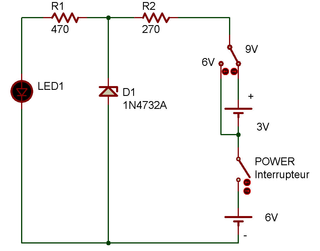
When you've wired the project, set the power switch to the up position, apply 9 V to the circuit, and check the brightness of LED 1.
Do the same check by setting the power switch to the down position and applying 6 V to the circuit. The brightness didn't change, as you noticed. So, you have understood a simple voltage regulating circuit using a zener diode.
Here, you will apply the zener diode D1 with 6 V and 9 V, at different times, through R2, and check LED 1 for possible change in brightness. As you can see, LED 1 is applied with the zener voltage of D1 through R1.
Can you guess how the brightness of LED 1 changes when the circuit is applied with 6 V and 9 V. If the voltage across D1 is constant, the brightness of LED 1 will not change; if not constant, the brightness will change. Now, go ahead.

![]()