Various inverters
74HC00, 74HC02, LM324
Inverters are made in many different ways, and we're going to experiment with a few of them in this project.
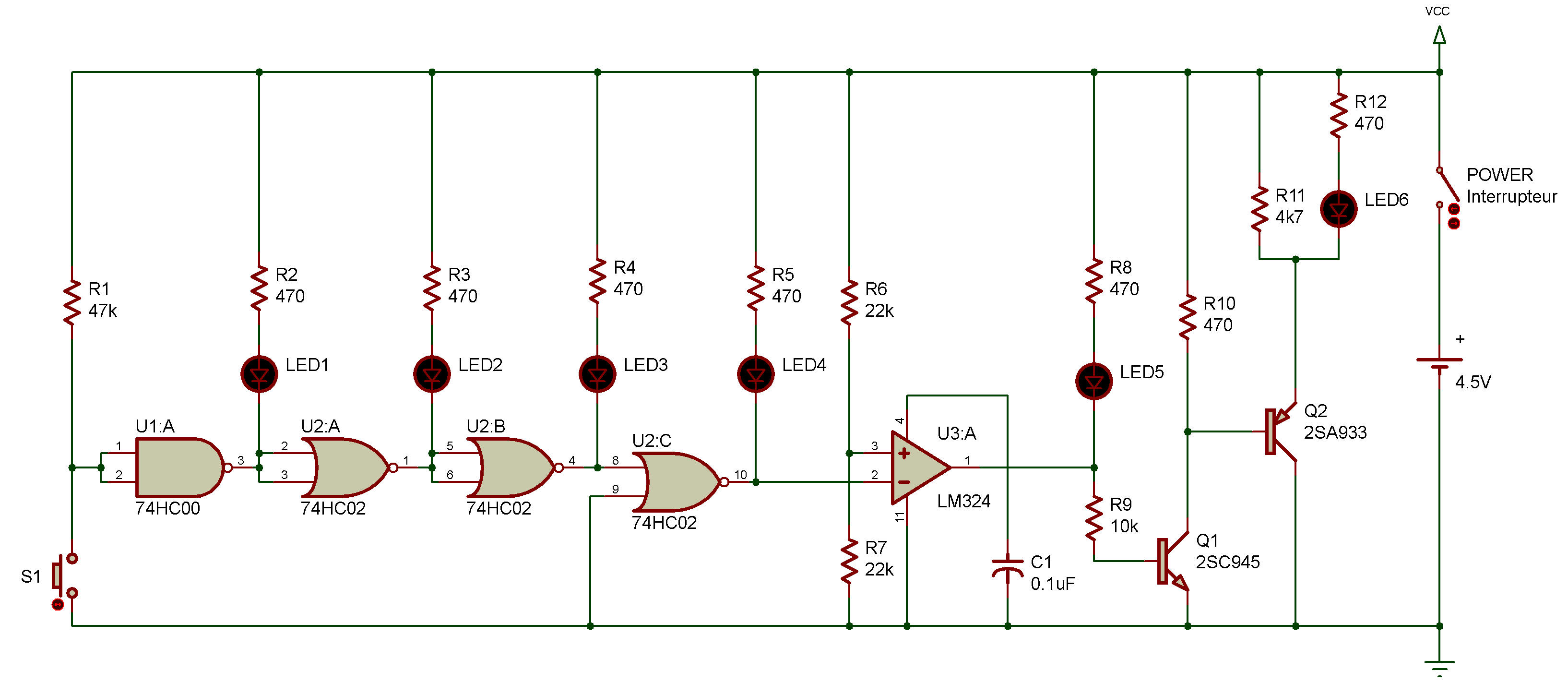
Look at the schematic for this project. LED 1 - LED 6 are used to display the output of each inverter.
LED 1 -LED 2 are used for the inverter using a NAND gate circuit, LED 3 - LED 4 for the one using a NOR gate circuit, LED 5 for the one using an operational amplifier, and LED 6 for the one using a transistor.
When you finish assembling, turn power ON and you'll see that the odd numbered LEDs light up (LED 1, LED 3, LED 5).
This is because the input of the first inverter is 1 when S1 is OFF.
Now press S1 to make the input to the first inverter 0. What happens to the LEDs?
LEDs with an even number (LED 2, LED 4, LED 6) light up this time. The project shows you that every other LED lighted up, and this means that each LED shows the action of each inverter.

![]()