Multivibrator switching of led display
The purpose of this project is to show how an LED display may be controlled with a freerunning multivibrator. Since this circuit causes the numbers 1 and 2 to flash alternately ON and OFF, it reminds us of some neon advertising signs with flashing, eye-catching ads.
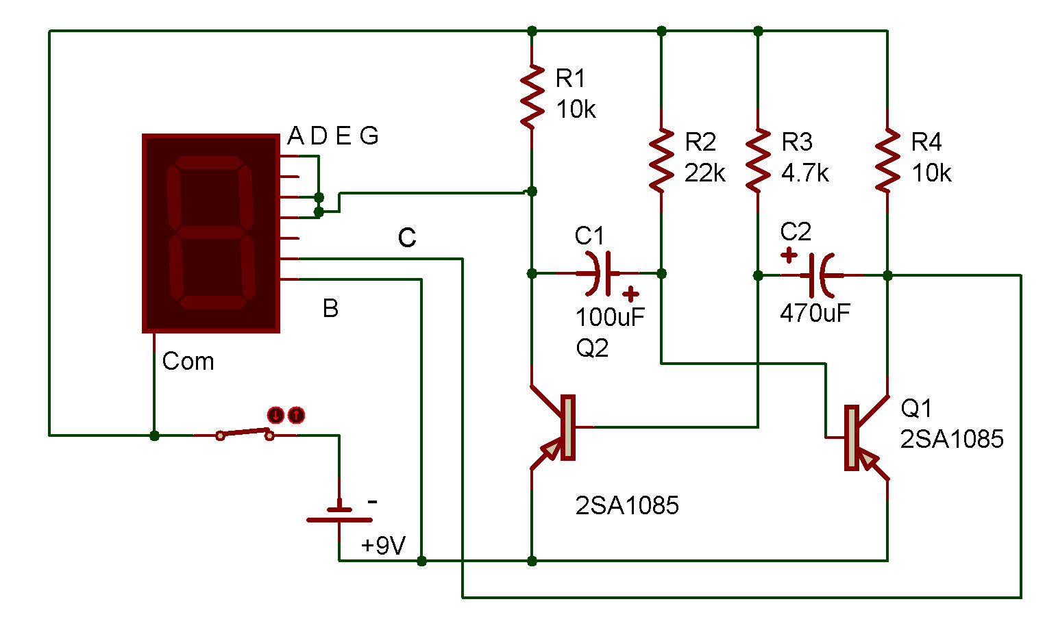
Here the LED is controlled by a free-running multivibrator to power the correct segments, giving a continous alternation of the numbers 1 and 2. The multivibrator uses Transistors Q with four Resistors and two Capacitors to produce two out-of-phase square waves to drive the LED segments.
When the Q(1) is ON, the Q(2) is OFF, and vice versa. This ON and OFF operation is accomplished automati cally, due to the alternate charging and discharging of the 100uF and 470uF Capacitors.
For example, as the 470uF is receiving a charge through its 10K Resistor from the negative 9V Battery terminal, this charging current is caused to flow through the base emitter junction of the Q(2), turning it ON. After a very short time, the Capacitor is charged, but the 47K Resistor keeps the Q(2) ON.
During all this time the charge which is in the 100uF is slowly discharging through the 22K, Battery and Q(2). The voltage on this Capacitor will hold the Q(1) in the OFF state until it discharges to a point where it cannot hold the Q(1) OFF any longer. At this point the circuit "flips", and the 100uF begins to charge, turning the Q(1) ON.
Now the functions of the Capacitors (and Transistors) are reversed so that the Q(1) is quickly turned ON by the 100uF, and the Q(2) is turned OFF by the 470uF. After a short time the circuit action switches or "flops" back to the opposite state as the 100 uF reaches the end of its discharge.
When the Q(2) is ON, the A, E, D, B and G segments of the LED light to form the number 2, and when the Q(1) is ON the B and C segments light to form the number 1. Notice that is both instances the B segment lights, due to its direct connection to the (+) terminal of the Battery.
You can measure voltages across any component in this circuit with your VOM while watch ing the LED operation. Thus you can verify the circuit explanation and you can learn how it works. This is a popular circuit so you will see.
Some of the different experiments you might want to try are:
different size Capacitors to see their effect on the speed of operation; rewire the LED to display numbers other than 1 and 2. You may try different, higher values in place of the 22K and 4.7K.
Do not use lower values for any of the Resistors or you may damage the Transistors.

![]()