Logic NOR Circuit (Part 1)
This project is a demonstration of the logic NOR function. The NOR function is like the OR function except the output conditions are reversed (or inverted). The logic NOR function is used extensively in computers and hand-held calculators. It is usually tucked away inside the circuitry as an obscure but important part of the logic circuit.
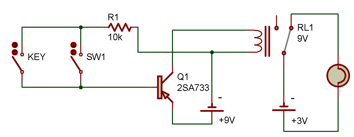
The circuit operates as follows:
1. When neither one switch nor the other is closed, the Lamp is ON.
2. When either or both switches are closed, the Lamp is OFF.
This circuit accompiises this function by wiring the Relay contacts so that the Lamp is normally ON. To bias the Transistor ON, the switches must be closed to feed the base current to the Transistor. The Transistor in turn controls the Relay.
The NOR Truth Table and additional discussion on the NOR function are included in projects Logic NOR Circuit (Part 2). Before you refer to them, try to make a Truth Table for the NOR all by yourself.

![]()