How a line decoder works
7400, 7476
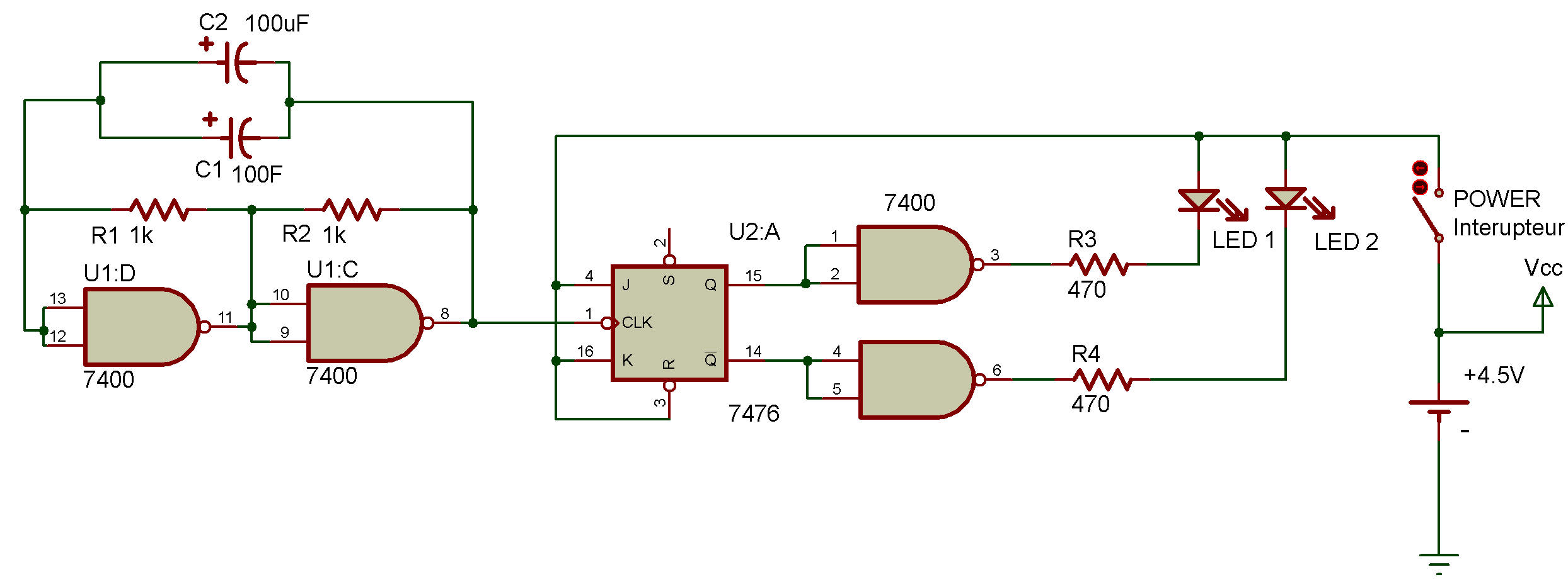
Line decoder can be a bit confusing when you're working with many flip-flops and their outputs. Let's back up a moment and take a look at a simpler counter and line decoder circuit.
In this Project we have a NAND multivibrator inputting a clock signal into a single flip-flop. You can easily guess what happens ... each time the clock signal is input, the flip-flop either sets, or resets.
Suppose that output Q is 1 while
Ǭ is 0. Both of these outputs go to NAND gates, where they're used for both inputs.Put the power ON. If Q is 1, the output of the NAND will be 0, and LED 1 will light. Ǭ is 0 at the same time, so the NAND it is connected to will have 1 for an output ... and LED 2 will go out.
The next clock pulse from the multivibrator will cause this situation to reverse (or flip-flop!)
If you'll look back at the schematics for the counters with line decoder we've played with in previous Projects, you'll notice that each NAND gets one input from the first flip-flop and another input from the second flip-flop. These combined inputs turn the LEDs on or off as the two flip-flops set and reset.
We use NANDS exclusively in counter Projects. But do you think that we could make counter circuits out of AND, OR, NOR or XOR gates?
You might want to get some scratch paper and try to figure out how those digital circuits could combine the outputs of the flip-flop in this Project. Do you think NAND gates are the easiest way to make a line decoder?
Can you come up with a simpler method?

![]()